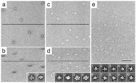
Fig. 1. Images of the TfR-Tf complex obtained with different negative staining protocols.

a and b: Images of an untilted (a) and a 60° tilted sample (b) prepared by the conventional negative staining protocol using uranyl formate. The particles are surrounded by a dark stain cloud, which is particularly evident in the image of the tilted specimen. Class averages (insets) show the two predominant orientations, in which the complex adsorbs to the carbon film, revealing a side view (inset 1) and a top view (inset 2) of the complex. c and d: Images of an untilted (c) and a 60° tilted sample (d) prepared by the carbon sandwich technique using uranyl formate. The negative stain forms a continuous layer and no stain cloud is apparent in images of untilted or tilted specimens. Class averages show that the complexes are seen in the same orientations as in the conventional negative staining protocol (insets 1 and 2). Due to the additional carbon layer, a significant number of complexes are being squashed upon drying and therefore can not be used for structure determination (insets 3 and 4). e: Image obtained with an untilted sample embedded in a mixture of glucose and ammonium molybdate, showing the image contrast to be much weaker than in the case of uranyl formate staining. Classification of particles selected from such images reveals that the molecules adsorb to the grid in random orientations. Some of the resulting class averages are shown in insets 1 to 10. The lines in panels a to d indicate the tilt axis. The scale bar corresponds to 50 nm and the inset panels have a side length of 26 nm.
