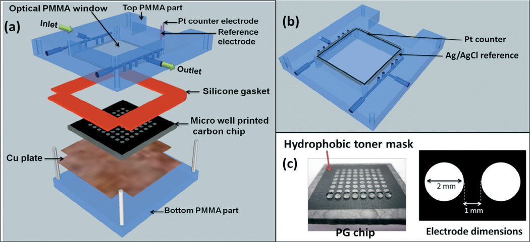
Scheme 2.
ECL chip and the fluidic reaction chamber, (a) component assembly into the flow cell, (b) underside view of reference and counter electrode wires in the top poly(methylmethacrylate) (PMMA) plate, (c) pyrolytic graphite (PG) chip with printed microwells. The first row is shown containing 1 µL water droplets.

