Abstract
A new model has been established in the domestic pig for neural prosthetic device development and testing. To this end, we report on a complete neural prosthetic developmental system using a wireless sensor as the implant, a pig as the animal model, and a novel data acquisition paradigm for actuator control. A new type of stereotactic frame with clinically-inspired fixations pins that place the pig brain in standard surgical plane was developed and tested with success during the implantation of the microsystem. The microsystem implanted was an ultralow power (12.5mW) 16-channel intracortical/epicranial device transmitting broadband (40kS/s) data over a wireless infrared telemetric link. Pigs were implanted and neural data was collected over a period of 5 weeks, clearly showing single unit spiking activity.
I. Introduction
Modern medical device development has improved the lives of countless injured or diseased individuals. For example, more than 400,000 cardiac pacemakers are implanted every year in the U.S. (>4 million implanted in total) [1]; over 200,000 total hip replacements trade titanium for bone, allowing people to walk and run again after traumatic limb injury. Developers of these devices (and myriad others) were confronted by challenges unable to be first addressed in humans directly. Instead, animal surrogates were used to validate the longevity, mechanical stability, biocompatibility, and ultimately efficacy of these devices. Without appropriate models it is unknown how long the translation process would have been from concept, to experimentation, and eventually, commercialization. Brain-machine interfaces (BMIs) are no different; they hold the potential to increase dramatically the quality of life for individuals suffering from brainstem stroke, advanced ALS, locked-in syndrome, and they face the same translational and development challenges.
For centuries, the preferred animal species for the field of neuroscience have been both rodents and primates. In rodents, neuroscientists gained incredible control over gene expression as early as 1974 [2], which led to fundamental breakthroughs in basic architecture and chemical signaling in cortical circuits. However, the morphology (lack of gyral patterns and size) of the rodent brain has prevented it from being a particularly good comparison to the human brain for many research directions. Non-human primates are regarded as the penultimate animal model for neuroscientific study and have been used extensively in the studies of higher cortical processing and neurological disease treatment. However, it is exactly their closeness to humans that can make working with monkeys ethically complicated and costly.
Indeed, there is a critical need for a large animal model with complex sulcogyral topography and ethically more acceptable for study. Within other research areas, such as toxicology (Lehmann, 1998), diabetes (Larsen and Rolin, 2004) and experimental surgery (Richer et al., 1998), the use of swine has increased dramatically over recent decades. The emergence of pig experimental models reflects the considerable resemblance of the pig to the human neuroanatomy and physiology. In addition, pig is widely available due to commercial production, leading to development of standardized laboratory pigs. These have considerable ethical and economic advantages over primates. An extensive evaluation of pigs in neuroscience was recently compiled [3] and provides and excellent comparison between commonly used species used in neuroscience.
This paper presents a novel use of laboratory pigs as a model for neuroprosthetic device development. We employ the pig model to (a) evaluate a previously published ([4], [5], [6], [7]) wireless cortical interface (Brain-Implantable Chip, BIC) developed over the last six years in our lab to record broadband neural data from shallow cortical circuitry (1mm); (b) evaluate a system of in-house electronics aimed at on-chip synthesis for neural data processing and prosthetic control - a system labeled Embedded System for Prosthetic Application; and (c) evaluate longevity, efficacy, and mechanical stability of the implant in statistically significant numbers, unachievable by number in primates and relevancy in rodent studies. This paper is organized into the following sections: Section II elucidates the design of a new pig stereotactic apparatus and its use in our device development studies. Section III describes the fully implantable wireless neural recording platform employed in this study including design choices, the fabrication process, and packaging challenges. Section IV introduces a platform on which to build mutable data processing algorithms, decoders, and actuators for neural prosthetics.
II. Development of a Large Animal Stereotactic Frame
A. A brief history
Scientists and philosophers have for centuries been attempting to visualize and understand the architecture of the brain. Not surprisingly, there is much debate about the first approaches in reproducibly exposing neural targets. While there is much discourse about the history, most start with the apparatus constructed by Carl Dittmar in 1873 [8] who constructed a frame for accessing the medulla oblongata. However, the first truly stereotactic frame (Cartesian coordinates), was made by Horsley and Clarke in 1908 [9] and later adapted for human use by Mussen in 1918. While these apparatuses were mechanically interesting, they were not widely used. The emergence of modern human stereotaxis started with the frame designed by Spiegel in 1947 [10] for inserting a wire cannula into subcortical regions with minimal injury. Speigel, in addition, defined the surgical plane of reference to be the line drawn between the inferior aspect of the orbit and the upper border of the external auditory meatus; two locations easily visible and accessible by a surgeon and fixed within the individual (also referred to as the Frankfurt Plane).
While the surgical procedures have changed a great deal since 1947, the basic principals of Spiegel’s frame have not. One approach that has changed, and that we employ in our design of a large animal stereotaxic frame, is using shape pins to fixate the subject to the reference coordinate system.
B. Custom frame design
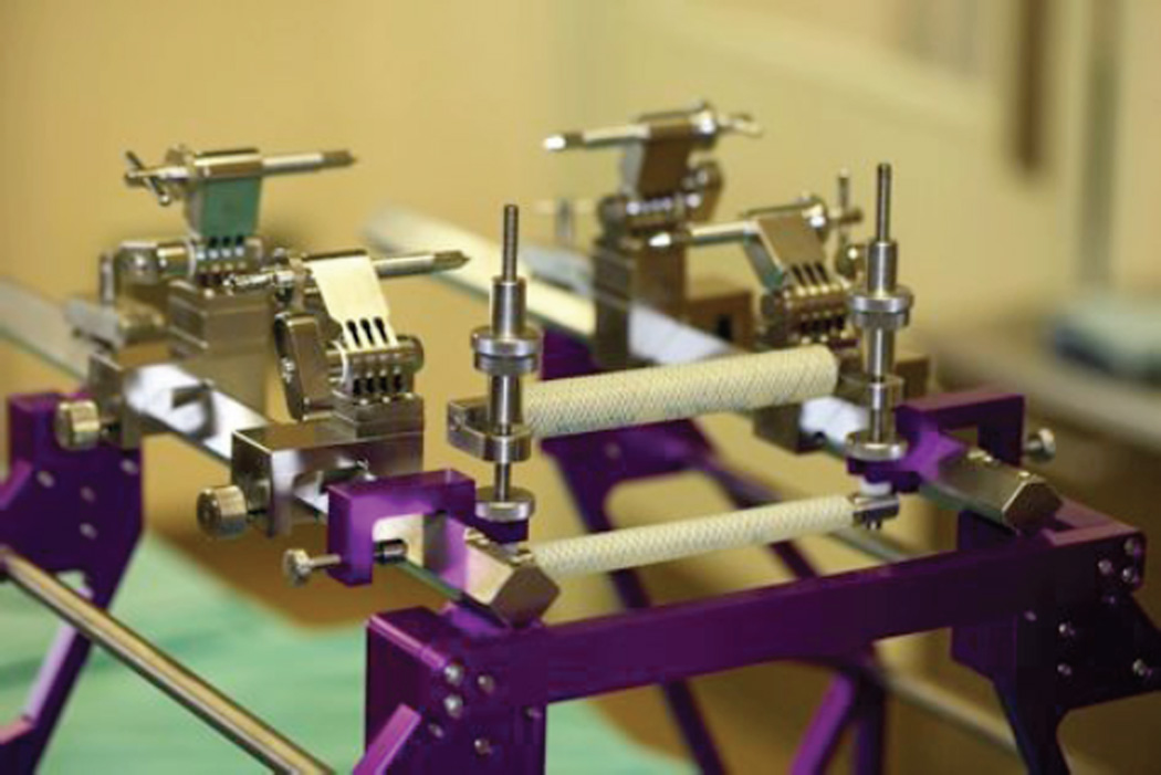
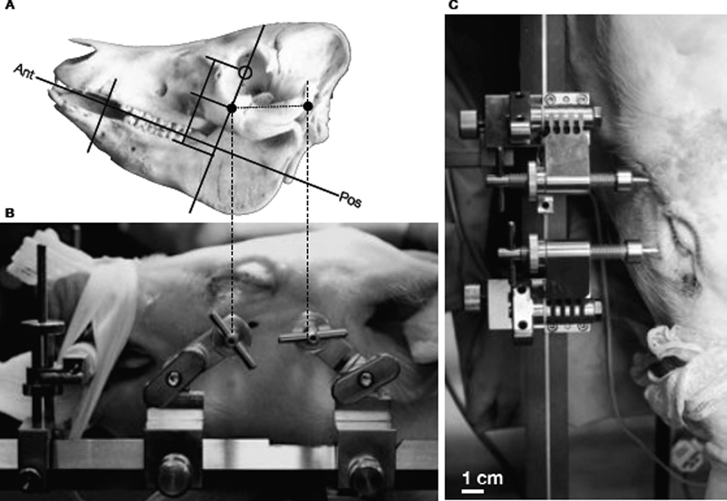
Modeled after human neurosurgical frames, we developed a four-pin system that attaches to the standard Kopf longitudinal bars and secures the skull (figure 1. The pin support system is made from 316 surgical steel and electroplated in TiN to reduce friction and extend lifetime in steam sterilization commonly used in operating rooms. While a base unit supports the pins and attaches them to the frame, the pins themselves are threaded and advanced through the skin and into the zygoma on each side of the skull as well as along the zygomatic process of the temporal bone near the auditory meatus. The two pins in the zygoma support most of the weight of the head and neck, while the two more posterior fixation pins prevent rotation about the zygoma as seen in Figure 2. The tips of the pins have been made modular, as different geometries may be desired for various animal ages, species, etc. We have chosen a 5mm length tip with a 2mm base and a 5mm diameter shaft. The tip length was estimated from post-mortem pig skulls of similar aged pigs; the angle of the taper was estimated from human neurosurgical fixation pins to reduce compression of the bone during insertion into the skull.
Fig. 1.
An image of the large animal stereotax frame developed in conjunction with surgeons and machinists at a local precision machine-shop. Longitudinal bars are standard Kopf dimensions with custom supports (purple) to accommodate animals as large as 35kg pigs. The frame base is attached to the patient table before placing the animal on the field, then the top of the frame is lowered and secured into place after anesthesia equipment and life-support are secured. While the image shows the muzzle clamp, this was not needed nor used in our experiments as the fixation pins proved to be extremely stable.
Fig. 2.
Placement of stainless steel pins for complete head fixation. The skull of a 30 kg Yorkshire pig was measured and analyzed to estimate placement of pins for stable fixation (a) relative to obvious features, such as the center of the pupil and the auditory meatus. The custom set of TiNcoated stainless steel commissioned by Kineteks LLC (Warwick, RI) were inserted into designated locations on both sides of the skull. Side view (b) and top view (c) give a sense of the stability achieved and specific locations chosen. Though not evaluated quantitatively, the stability of the four pins far surpassed that of the standard ear-bar plus nose clamp most often used.
III. A Description of the Implant
A. The BIC Microsystem
While great advances have been made in neural prosthetic device development, such as the percutaneous head-mounted wireless neural recording systems reported by Stanford University [11] and others [12], the ultimate goal in neural prosthetics as well as fundamental brain science envisions a fully implanted wireless and broadband system for high-performance chronic brain communication interfaces. This implies a truly embedded brain-interfaced microsystem, where any number of neural sensors, including the active microelectronic circuits, are sealed within the subject’s ultimately protective envelope, the skin. The neural signals are broadcast transcutaneously i.e., without any skin-penetrating wires or feed-through connectors, whatsoever. A fully implantable, wireless system presents formidable biomedical engineering device challenges. Its benefits include elimination of the infection risk which is inherently present with any percutaneous connections, reduction in the mechanical vulnerability of the skull-mounted modules to accidental impact (e.g., moving animal or epileptic patient), and a host of clinical and health care benefits that are especially applicable to human subjects and patients.
Within the cortical frontend of the BIC, the silicon microelectrode array (MEA) is directly flip-chip bonded to a ultralow-power analog ASIC chip which houses preamplifiers addressing each channel (microelectrode) across the entire neurally-relevant bandwidth (0.1 – 7.8KHz) and a multiplexing circuitry for data serialization. The integration of the analog preamplifiers with the MEA is important in order to minimize the distance raw analog signals must travel before amplification. Performance parameters of the chip include gain of 45.6dB, bandwidth 0.1Hz – 7.8kHz, referred-to-input noise (RTI) 8.5µVrms (0.1Hz – 100kHz, while others, [13], [12], [14], have shown down to 3.6µVrms and lower is a broader band), and a 1Gbps vertical cavity surface emitting laser (VCSEL) for data telemetry. Further details of its design are described elsewhere [6], [4], [15], [5], [7]. The experiments described here have been conducted with a 16-channel system for logistical reasons, while to a 100-channel system is also currently being used in our labs. Much of the inspiration for these analog ASIC designs has been derived from prior and parallel work by Harrison et al. [13], [12]. However, we impose strict design criteria that the power dissipation of the ASIC (100-channel based microsystem) chip does not impart heat to the cortex that exceeds 0.1°C in the tissue within the volume accessed by the neural probes.
The backend cranial unit is fabricated by assembling a dedicated A/D chip and a digital ASIC command/control chip on the same substrate plane that also houses a microcrystal semiconductor laser (VCSEL) for transmission of the digitized serial broadband neural signal data stream through a subject’s skin at 852 nm (in the infrared IR). Among the advantages of the IR wireless transmission modality is the very large bandwidth, which modern optical transceiver systems possess (1Gb/sec, if needed). Transmission through a subject’s skin (Yorkshire pig) causes scattering, but a conventional photodiode is still able to pick up the digital stream when placed within 2 mm of the skin surface. On the opposite side of the substrate is a planar RF receiving coil for enabling inductively coupled (transcutaneous) receiving of power and clock to the microsystem.
B. Microsystem packaging
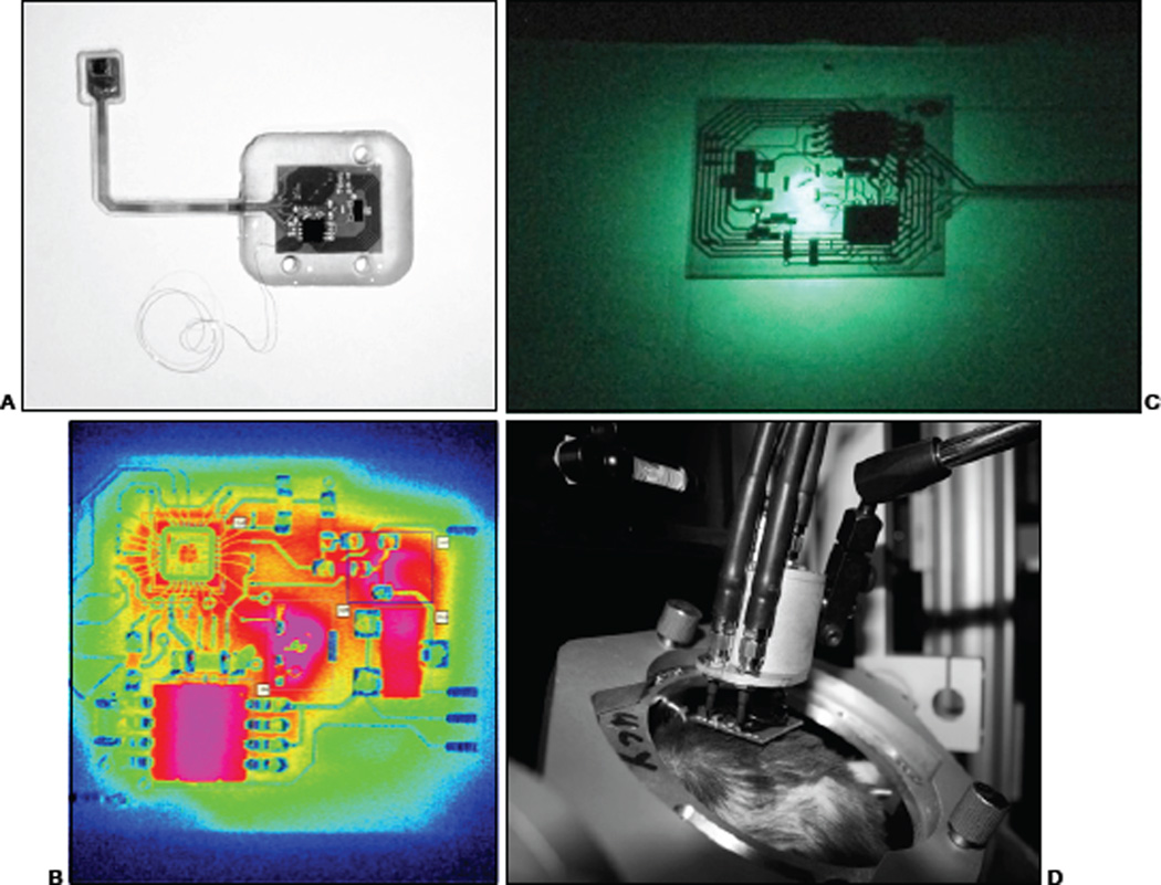
Medical devices aimed at long-term functionality and reliability require both mechanical robustness and ionic protection. While both are often addressed by using metal hermetic enclosures (laser-joined titanium or ceramics, such as pacemakers, deep-brain stimulators, etc.), when a system must maintain flexibility along with the above characteristics, polymeric or very thin crystalline insulators are required. While visual prosthetics have been constructed using thin layer semi-crystalline encapsulants [16], [17], here we use polymers. Systems are first cleaned in a series of ultrasonic baths for 3 minutes in each of MS-722 (Miller Stevenson, 1 cm CT), De-ionized and filtered water, and Isopropyl alcohol with drying in-between and are finally baked at 100°C for 10 minutes. Prior to silicone application, the surface is activated by application of a silicone primer (CF1–134). The entire microsystem is then potted in poly-dimethyl-siloxane (NuSil R-2188) for electrical isolation and mechanical flexibility. Careful control of silicone thickness must be maintained to assure flexibility in the tether and prevent buildup or wicking on the electrode array. For images of the structure after encapsulation, see [6] and figure 3A.
Fig. 3.
The IR sensor is a IrSb-based camera with a sharp low wavelength cutoff at 3µm and a high cutoff at 5µm. Therefore, it is very unlikely there is any influence (directly) from the VCSEL output (852nm) which, also has a very sharp peak at the cavity resonance. (Left) Unpackaged BIC microsystem 10 seconds after turn-on at 30mW delivered power over 13.56MHz carrier. Pink values are hot (in terms of photon count / time). (Right) Sum photon count over time for each of the 5 regions selected. 1: Tank circuit, 2: Half-wave rectifier, 3: Paula chip, 4: ADC, and 5: VCSEL (25 frames / second 30 seconds).
The main functions of the encapsulation are to ensure (i) that electrical leakage current to the adjacent tissue is minimized, and (ii) ionic leakage from the tissue to the electronic components is less than 10pA. For chronic implant applications, this presents a formidable challenge for all researchers in the field of implantable neural prosthetics and has been studied to a degree [18], [19], [20], [21], [22]. We view our initial approach, using PDMS (NuSil R-2188), as a useful starting point for sub-chronic or short-term (1 to 3 months) in-vivo animal testing. In addition, we have designed and implemented an encapsulation test unit (ETU), which simulates the topographical, thermal, and electrical stresses put on the encapsulant to test leakage current and component functionality over extended periods of soak time. This test system allows us to evaluate and characterize potential encapsulants under realistic conditions.
C. Surgical implantation
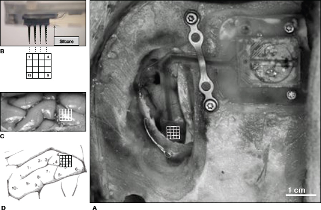
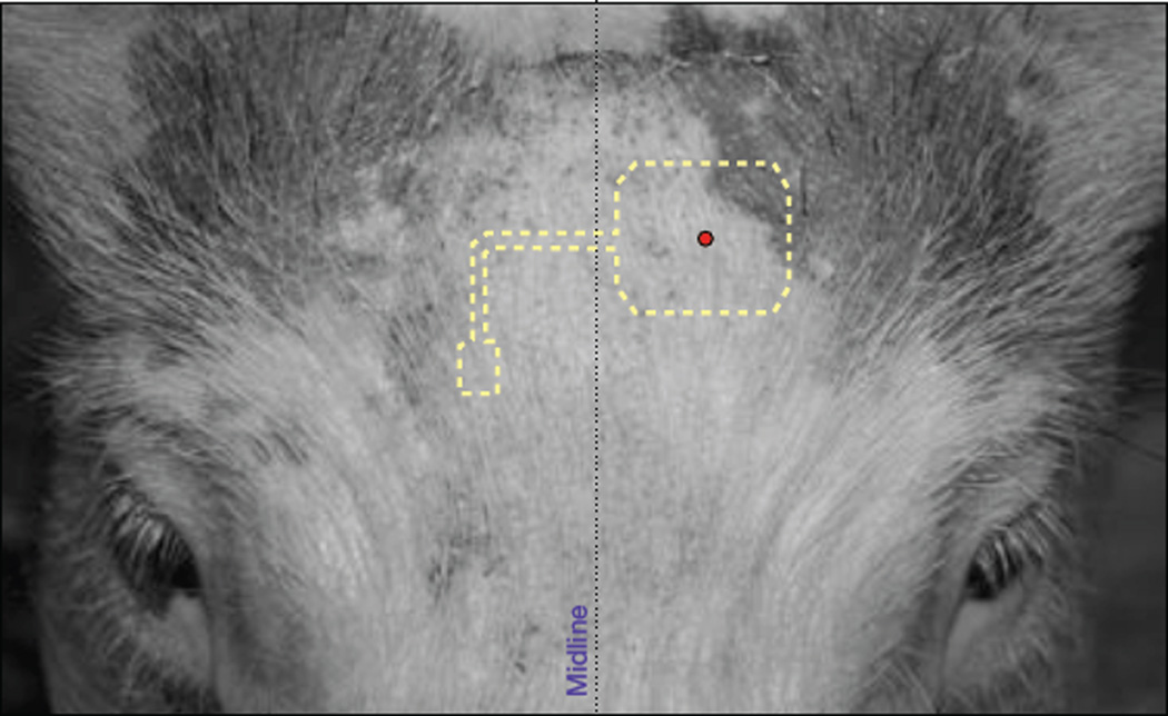
All procedures described here were approved by the Institutional Animal Care and Use Committee (IACUC) and were conducted in a sterile environment. An arched skin incision was made from the left posterior aspect of the head anteriorly returning to the right posterior aspect. This notably long incision was made to gain maximal access to craniotomy site (R parietal lobe) while at the same time moving the suture line away from the implant to reduce chances of irritation. Separation of the galea aponeurotica from the skull (and skin) was done in case a dural graft was needed to complete closure. A Stryker (USA) cranitome was used to turn a 3cm ×1cm craniotomy above primary somatosensory cortex - specifically the area controlling the rostrum [23] (see figure 4). After the durotomy was completed, the microsystem was positioned for insertion. Insertion was made through the arachnoid and pia mater by a commercially available pneumatic inserter (Blackrock Microsystems, UT) with a 1.5 mm spacer - the electrodes on this system have a 1.5 mm shank length. The craniotomy was then closed with the remaining bone flap and secured with medical-grade Ti mesh and screws (Stryker). This process has been used by numerous groups with high-percentages of success [24], [11], [25], [26].
Fig. 4.
Surgical image of microsystem implantation in pig (a) where the telemetric unit is attached to the skull with two Ti screws, the interconnecting tether is protected by a titanium dog-bone and lays gently on the cortex running A–P. The array is shown inserted with a grid superimposed for reference to b–d: a diagram of electrode implantation location into the primary sensorimotor cortex. The 16 electrodes are about 1mm in height (after PDMS packaging) and thus were embedded that distance into cortex.
One notable difference when implanting a completely wireless system is that the skin is completely sutured closed with no percutaneous connections as are normally found when implanting microelectrode arrays or really any neural recording device. Since swine use their foreheads as shovels, any protrusion of the implantation would not be tolerated. This animal model pushes the limits of robustness compared to humans, for whom a neural prosthetic would be more amenable.
D. Results
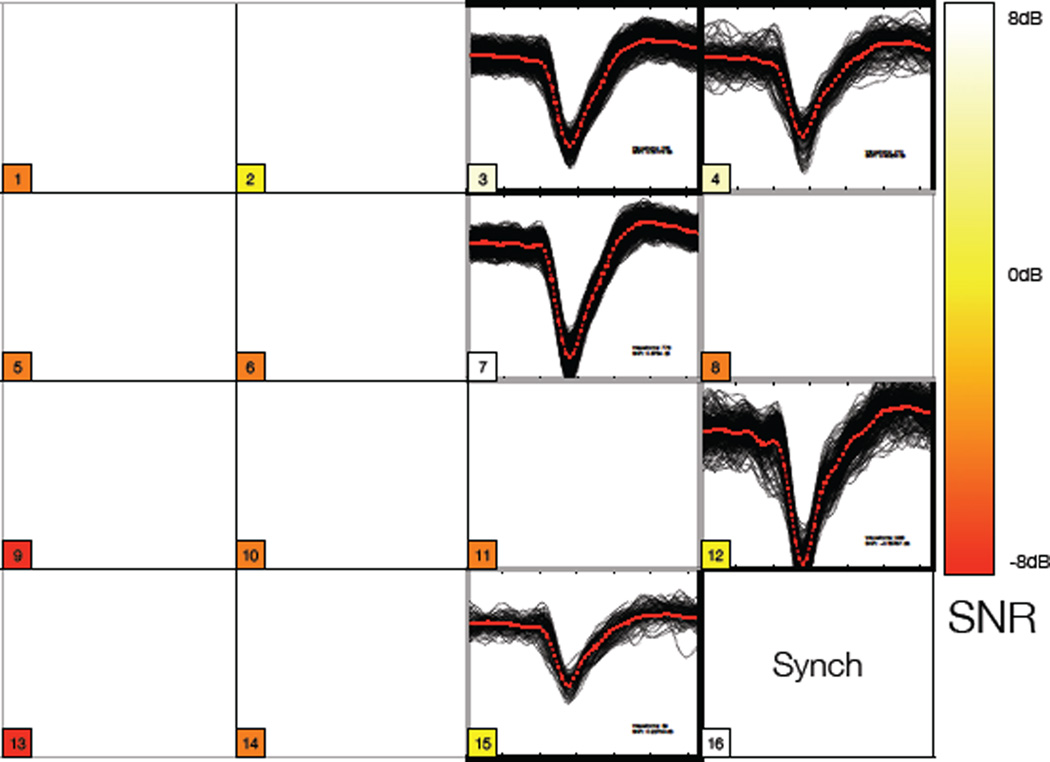
Four pigs have been implanted over the last three months. While the first two were critical in developing the proper surgical procedures, the most recent animals have provided stable, completely wireless, broadband neural recordings for 50+ days combined. Figure 2 depicts the surgical procedure bringing the pig in Frankfurt plane for stereotactic surgery. The custom stereo-taxis fixation pins based on human stereotactic models which was extremely successful in holding the head and exposing the surgical field. After a 6-day post-implantation surgical recovery period, we were able to record neural activity (figure 6). We are now at 32+ days post recovery, and in each recording session clear spiking activity has been demonstrated. We are encouraged by these results and this model as a method of providing clear steps toward successful clinical trials.
Fig. 6.
Overlaid waveforms collected over 1 minute of recording from the R rostrum area of pig cortex from a 16 channel wireless system. The input of channel 16 is overwritten as a synchronization signal in the controller to maintain channel order for data decomposition and error checking in the receiving hardware. Colored blocks (or shaded regions if BW print) describe the SNR - darkest being poor SNR and lightest being best SNR. All measurements in dB. Best measured ratio was 6 dB. Five channels (3, 4, 7, 12, and 15) showed spiking activity on this system (A). Many of the remaining channels simply exhibited poor SNR and were difficult to record any meaningful data.
IV. Introduction of Embedded Systems for Prosthetic Applications
Significant improvements in implantable recording microsystems have given us access to a much richer source of neural data. This technology has made much more feasible the ultimate goal of developing upper-limb prosthetics capable of utilizing brain-originated signals communicated wirelessly to them, in order to execute movements. Despite these advances, neuroprosthetic systems are still far from having widespread application in a clinical setting. We have begun to address some of the issues that are associated with developing clinical neuroprosthetic devices within an embedded system framework. The purpose of an embedded system for prosthetic application (ESPA) is to (1) standardize the way we communicate with a prosthetic, (2) miniaturize all of the hardware and software necessary to perform such a task, and (3) create a common platform that allows for modularization in the design and utilization of all of our computational needs.
A. Computational considerations
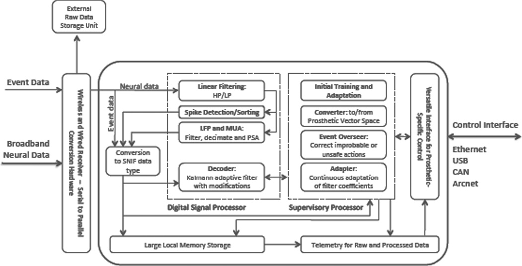
The computational complexity of the algorithms involved in finding the correlation between neuronal activity and motor commands is not trivial. In a standard decoding flow, we begin with our input signal (i.e. raw, broadband neural activity - data flow shown in figure 7). For a 100- channel recording microsystem with a sampling rate of 40kHz/channel and 14-bit resolution for each sample, the input rate is 56Mbits/s. In order to extract spiking information from this raw trace, we first filter the data to extract any information in the higher frequencies, and at the same time eliminate low frequency noise. Applying an FIR filter of length N to each channel of our input signal results in N multiplications and N-1 additions for every sample. This corresponds to 4 ×10⁶·N multiplications and 4 ×10⁶·(N −1) additions every second. From this filtered trace, we then extract and sort action potentials by their characteristic waveforms. The simplest detection mechanism amounts to a comparator, and therefore its computational cost is negligible. However, sorting methods vary greatly in complexity. A manual spike-sorting algorithm that uses window discriminators has negligible computational cost. On the other hand, even a simple automated spike sorter can easily be the most computationally expensive component of the decoding sequence. A typical automated sorting algorithm first extracts features from an action potential waveform and then uses a distance measure to classify the spike. The associated cost of classifying a spike is a function of the number of existing clusters and the complexity of the distance measure. Once the waveforms are sorted, we can compute the firing rate of all of the units from which we are recording. A decoding mechanism, such as a linear Gaussian state-space representation (Kalman filter), is then used to find a correlation between the firing rates of the neurons and the kinematics of the limb of interest. The Kalman filter is a collection of linear equations that are updated recursively at every time step. The theoretical complexity of a single recursion of the Kalman filter for decoding an s-dimensional state vector with an n-dimensional observation vector is O(s3 +s2n+sn2 +n3) [27]. In this case, the size of the output state vector depends on the device we are trying to control while the observation vector depends on the number of units (i.e. neurons) that we are ”listening” to. This computation is something that we (as well as others) currently do in software, on several different computers and digital signal processors (DPSs). The end goal of ESPA is to move this computation away from the inefficiencies of its software implementation and into an embedded system.
Fig. 7.
Data flow and detailed diagram of internal architecture of the Brain Phone hardware. Specifically, the digital signal processor handles the filtering, spike detection and sorting, slow potential changes, and decoding algorithms which the supervisory processor handles the oversight of the system. Data is converted into SNIF (Standard Neural Interface Format) files to allow ease of data flow and probing (sniffing) of data throughout the function of the system. Prosthetic-specific vector space conversion will be uploaded to the Versatile Interface for Prosthetic Control unit diagramed above.
B. Matlab/Simulink: A development environment for ESPA
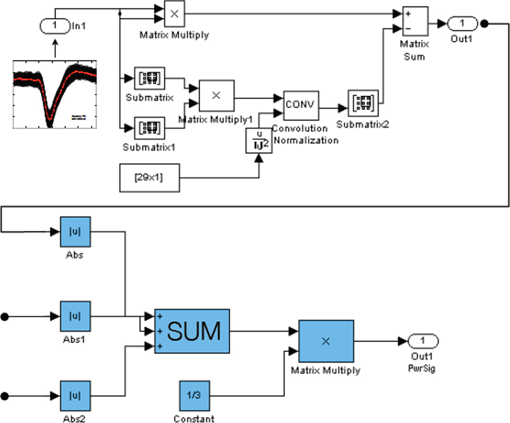
An important component of ESPA is the standardization of the signal processing methods and algorithms that are used in analyzing neural data. In the context of neuroprosthetics, typical methods include data filtering, spike detection and sorting, as well as a variety of decoding algorithms. In order to unify the way that these different algorithms are implemented and utilized, we take advantage of the Simulink development environment for model-based design. This software provides the user with a customizable set of block libraries that can be used to carry out any user-defined function. We have put together a Simulink block library that is rich with user-defined blocks useful in analyzing neural data. In figure 8, we show a Simulink implementation of the Multiscale Teager Energy Operator (MTEO) [28] - an algorithm that is used to facilitate the spike detection and extraction process. The ESPA Simulink block library gives users the ability to simply drag-and-drop different signal processing tools into their models, allowing for very modular system assembly. The motivation for using Simulink – as opposed to other software – is twofold. We can take advantage of the parallel processing capabilities built into Simulink in order to perform computationally expensive processes in real-time. This of course is a necessity for prosthetic applications. Furthermore, we can also take advantage of the code generation capabilities available through Simulink in order to deploy our prosthetic control models on an embedded system. This will allow for a lower-power, compact, computationally efficient modular neural-processing system.
Fig. 8.
An implementation of MTEO in Simulink. In this figure we can see what lies underneath each block. The properties of the block can be defined using custom written code or by simply using the built-in blocks within Simulink. The data flow shows neural data coming in as the input, the energy operator being performed on each input channel (shown 3 here), the output power signal. This is simply and example using one operator, but the significance of the system is that the data structures allow virtually any operator to be dropped in its place along this data flow.
C. Verifying the ESPA Topology with Animal Data
After implantation of the BIC microsystems detailed in section II, we recorded neural activity in each animal over an interval of 1 to 5 weeks. For recording, we used a custom data acquisition hardware system, which transfers data to a PC over high-speed USB 2.0. We wrote custom drivers to link our hardware with the display and recording software for visual analysis. All data was written to a format, which the platform described above takes as input. Data was then processed, offline, through the same Simulink– / Matlab–based model, including the MTEO and spike extraction steps to reveal the waveforms in the figure above. This data was piped exactly how it would be in an implementation of an embedded system so that we could verify each step of the processing. This system was able to filter, extract, sort and correlate neural activity from the pig primary somatosensory cortex.
V. Conclusions and Future Work
As we pursue translation of engineering and technological breakthroughs from the laboratory into the clinic, we must take every opportunity to prove functionality, reliability, and efficacy of the devices we produce. Until recently, the utility of the domestic pig appears to have been neglected in providing a simple, flexible platform for testing these attributes. Here we have described the use of a novel stereotactic frame, and its use in neuroscience and neuroprosthetic device development using this relatively unexplored animal model. Stereo-taxis and fixation was achievable with minimal effort and enabled implantation of a device under study in all four of the studied animals. In addition, we showed that a wireless, fully implantable neural sensor platform could be implanted into such an animal model and the data collected used for pre-clinical device verification. Our success in collecting neural data from these implanted systems further defines the utility of this domestic farm animal as a potentially holding a prominent role in neurotechnology. Four wireless devices were implanted a total of 50+ patient days in our initial trials and have been regularly recorded from over that period. Finally, motivated by the improvement in recording microsystems, we reported on the progress of system level project developing an embeddable platform that captures wireless data and will integrate all of the electronic components of a neuroprosthetic data acquisition system into a compact, wearable external unit for future patient mobility.
While this initial device development model has proven successful, it far from complete. We must scale the neural recording platform to acquire more channels in order to gain access to more neurons and potentially a greater landscape neural processing. In addition, as our goal is prosthetic control, we must also integrate a behavioral task into this paradigm to allow for in vivo evaluation of the actuator control algorithms. Perhaps this can be integrated into the pig model, but to what extent remains to be seen. Lastly, while initial reliability and longevity of the implanted systems was encouraging, an exhaustive characterization of the failure mechanism must be completed for chronic use.
Fig. 5.
Microsystem superimposed over pig 3, 20 days post-operative. No signs of irritation or inflammation from device or implant-related tissue disruption. Recordings were made with a ”wand,” consisting of an RF coil (delivering power), and a photodiode (receiving data), gently placed on the skin surface. The figure impresses the importance and advantages of removing percutaneous connections from neural prosthetic devices in favor of less intrusive wireless telemetry.
Acknowledgments
The authors would like to thank Dr. Moses Goddard for his critical input in the development of pig stereotactic equipment, John Mills and Megan Billings from Kineteks (Warwick, RI) for their high-precision machining and design expertise. In addition, our consultants at Mathworks (USA) and the animal care staff at Brown University have provided exemplary assistance throughout the development process of this project. Lastly, our colleagues in the neuroscience department at Brown University, Carlos Vargas-Irwin, PhD, John P. Donoghue, PhD, and Leigh Hochberg, M. D. PhD for their guidance.
This work was supported in part by the National Institute of Health (NIBIB and NCMRR/NICHD) under Bioengineering Research Partnership Program (IR01EB007401-01), the Office of Naval Research under Neuroengineering Program (N0014-06- 0185), and the National Science Foundation under Biophotonics Program (0423566).
References
- 1.Buch E, Boyle NG, Belott PH. Pacemaker and defibrillator lead extraction. Circulation. 2011 Mar;vol. 123(no. 11):e378–e380. doi: 10.1161/CIRCULATIONAHA.110.987354. [DOI] [PubMed] [Google Scholar]
- 2.Jaenisch R, Mintz B. Simian Virus 40 DNA Sequences in DNA of Healthy Adult Mice Derived from Preimplantation Blastocysts Injected with Viral DNA. Proceedings of the National Academy of Sciences of the United States of America. 1974 Apr;vol. 71(no. 4):1250. doi: 10.1073/pnas.71.4.1250. [DOI] [PMC free article] [PubMed] [Google Scholar]
- 3.Lind N, Moustgaard A, Jelsing J, Vajta G. The use of pigs in neuroscience: modeling brain disorders. Neuroscience and Biobehavioral Reviews. 2007 doi: 10.1016/j.neubiorev.2007.02.003. [DOI] [PubMed] [Google Scholar]
- 4.Nurmikko A, Donoghue J, Hochberg L, Patterson WR, Song Y-K, Bull C, Borton D, Laiwalla F, Park S, Ming Y, Aceros J. Listening to Brain Microcircuits for Interfacing With External World— Progress in Wireless Implantable Microelectronic Neuroengineering Devices. Proceedings of the IEEE. 2010 Mar;vol. 98(no. 3):375–388. doi: 10.1109/JPROC.2009.2038949. [DOI] [PMC free article] [PubMed] [Google Scholar]
- 5.Song Y-K, Borton D, Park S, Patterson WR, Bull C, Laiwalla F, Mislow J, Simeral J, Donoghue J, Nurmikko A. Active Microelectronic Neurosensor Arrays for Implantable Brain Communication Interfaces. Neural Systems and Rehabilitation Engineering, IEEE Transactions on. 2009 Aug;vol. 17(no. 4):339–345. doi: 10.1109/TNSRE.2009.2024310. [DOI] [PMC free article] [PubMed] [Google Scholar]
- 6.Borton D, Song Y-K, Patterson WR, Bull C, Park S, Laiwalla F, Donoghue J, Nurmikko A. Wireless, high-bandwidth recordings from non-human primate motor cortex using a scalable 16-Ch implantable microsystem; Annual International Conference of the IEEE EMBS; 2009. pp. 5531–5534. [DOI] [PMC free article] [PubMed] [Google Scholar]
- 7.Song Y-K, Patterson WR, Bull CW, Borton D, Li Y, Nurmikko A, Simeral JD, Donoghue JP. A Brain Implantable Microsystem with Hybrid RF/IR Telemetry for Advanced Neuroengineering Applications. EMBC Submission. 2007 Apr; doi: 10.1109/IEMBS.2007.4352319. [DOI] [PubMed] [Google Scholar]
- 8.Blomstedt P, Olivecrona M, Sailer A, Hariz MI. Dittmar and the history of stereotaxy; or rats, rabbits, and references. Neurosurgery. 2007 Jan;vol. 60(no. 1):198–201. doi: 10.1227/01.NEU.0000249205.58601.05C. discussion 201–2. [DOI] [PubMed] [Google Scholar]
- 9.Horsley V. The structure and functions of the cerebellum examined by a new method. Brain. 1908 [Google Scholar]
- 10.Spiegel EA, Wycis HT, Marks M, Lee AJ. Stereotaxic Apparatus for Operations on the Human Brain. Science. 1947 Oct;vol. 106(no. 2754):349–350. doi: 10.1126/science.106.2754.349. [DOI] [PubMed] [Google Scholar]
- 11.Miranda H, Gilja V, Chestek C, Shenoy K, Meng T. HermesD: A High-Rate Long-Range Wireless Transmission System for Simultaneous Multichannel Neural Recording Applications. Biomedical Circuits and Systems, IEEE Transactions on. 2010 Jun;vol. 4(no. 3):181–191. doi: 10.1109/TBCAS.2010.2044573. [DOI] [PubMed] [Google Scholar]
- 12.Harrison R, Kier R, Greger B, Solzbacher F. Wireless neural signal acquisition with single low-power integrated circuit. Circuits and Systems. 2008 doi: 10.1109/TNSRE.2009.2023298. [DOI] [PMC free article] [PubMed] [Google Scholar]
- 13.Harrison R, Kier R, Chestek C, Gilja V, Nuyujukian P, Ryu S, Greger B, Solzbacher F, Shenoy K. Wireless Neural Recording With Single Low-Power Integrated Circuit. Neural Systems and Rehabilitation Engineering, IEEE Transactions on. 2009 Aug;vol. 17(no. 4):322–329. doi: 10.1109/TNSRE.2009.2023298. [DOI] [PMC free article] [PubMed] [Google Scholar]
- 14.Yin M. A low-noise preamplifier with adjustable gain and bandwidth for biopotential recording applications. Circuits and Systems. 2007 [Google Scholar]
- 15.Patterson W, Song Y-K, Bull C, Ozden I. A microelectrode/microelectronic hybrid device for brain implantable neuropros-thesis applications. Biomedical Engineering. 2004 [Google Scholar]
- 16.Stieglitz T. Manufacturing, assembling and packaging of miniaturized neural implants. Microsystem Technologies. 2010 Feb;vol. 16(no. 5):723–734. [Google Scholar]
- 17.Weiland JD, Liu W, Humayun MS. RETINAL PROSTHESIS. Annual Review of Biomedical Engineering. 2005 Aug;vol. 7(no. 1):361–401. doi: 10.1146/annurev.bioeng.7.060804.100435. [DOI] [PubMed] [Google Scholar]
- 18.Do MT, Auge J-L, Lesaint O. Dielectric losses and breakdown in silicone gel. Electrical Insulation and Dielectric Phenomena. 2006 [Google Scholar]
- 19.Edell D. Four IDEs will be located in a column at 200mm intervals along one of the center shafts with the closest approximately 500mm a. Insulating Biomaterials N01-NS-9-2323. 2004 Feb [Google Scholar]
- 20.Lawrence SM, Larsen JO, Horch KW, Riso R, Sinkjaer T. Long-term biocompatibility of implanted polymer-based intrafascicular electrodes. Journal of biomedical materials research. 2002;vol. 63(no. 5):501–506. doi: 10.1002/jbm.10303. [DOI] [PubMed] [Google Scholar]
- 21.Reddy S, Vadgama P. Ion exchanger modified PVC membranes—selectivity studies and response amplification of oxalate and …. Biosensors and Bioelectronics. 1997 doi: 10.1016/s0956-5663(97)00055-9. [DOI] [PubMed] [Google Scholar]
- 22.Otsuka K, Takeo Y, Ishida H, Yamada T, Kuroda S, Tachi H. The Mechanisms That Provide Corrosion Protection for Silicone Gel Encapsulated Chips. IEEE Tansactions on Components, Hybrids, and Manufacturing Technology. 1987;vol. 12(no. 4) [Google Scholar]
- 23.Sauleau P, Lapouble E, Val-Laillet D, Malbert C. The pig model in brain imaging and neurosurgery. Animal. 2009;vol. 3(no. 08):1138–1151. doi: 10.1017/S1751731109004649. [DOI] [PubMed] [Google Scholar]
- 24.Bansal A, Vargas-Irwin C. Relationships among low-frequency local field potentials, spiking activity, and 3-D reach and grasp kinematics in primary motor and ventral premotor cortices. Journal of Neurophysiology. 2011 doi: 10.1152/jn.00532.2010. [DOI] [PMC free article] [PubMed] [Google Scholar]
- 25.Acharya S, Tenore F, Aggarwal V, Etienne-Cummings R, Schieber M, Thakor N. Decoding Individuated Finger Movements Using Volume-Constrained Neuronal Ensembles in the M1 Hand Area. Neural Systems and Rehabilitation Engineering, IEEE Transactions on. 2008 Feb;vol. 16(no. 1):15–23. doi: 10.1109/TNSRE.2007.916269. [DOI] [PMC free article] [PubMed] [Google Scholar]
- 26.Zerris VA, Donoghue JD, Hochberg LR, O’Rourke DK, Chiocca EA. Braingate: Turning Thought into Action-First Experience with a Human Neuromotor Prosthesis: 885. Neurosurgery. 2005 Aug;vol. 57(no. 2):425. [Google Scholar]
- 27.Malik WQ, Truccolo W, Brown EN, Hochberg LR. Efficient decoding with steady-state Kalman filter in neural interface systems. IEEE transactions on neural systems and rehabilitation engineering : a publication of the IEEE Engineering in Medicine and Biology Society. 2011 Feb;vol. 19(no. 1):25–34. doi: 10.1109/TNSRE.2010.2092443. [DOI] [PMC free article] [PubMed] [Google Scholar]
- 28.Choi JH, Jung HK, Kim T. A new action potential detector using the MTEO and its effects on spike sorting systems at low signal-to-noise ratios. IEEE transactions on bio-medical engineering. 2006 Apr;vol. 53(no. 4):738–746. doi: 10.1109/TBME.2006.870239. [DOI] [PubMed] [Google Scholar]


