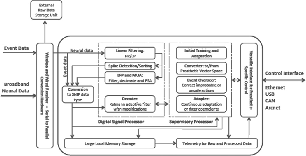
Fig. 7.
Data flow and detailed diagram of internal architecture of the Brain Phone hardware. Specifically, the digital signal processor handles the filtering, spike detection and sorting, slow potential changes, and decoding algorithms which the supervisory processor handles the oversight of the system. Data is converted into SNIF (Standard Neural Interface Format) files to allow ease of data flow and probing (sniffing) of data throughout the function of the system. Prosthetic-specific vector space conversion will be uploaded to the Versatile Interface for Prosthetic Control unit diagramed above.

