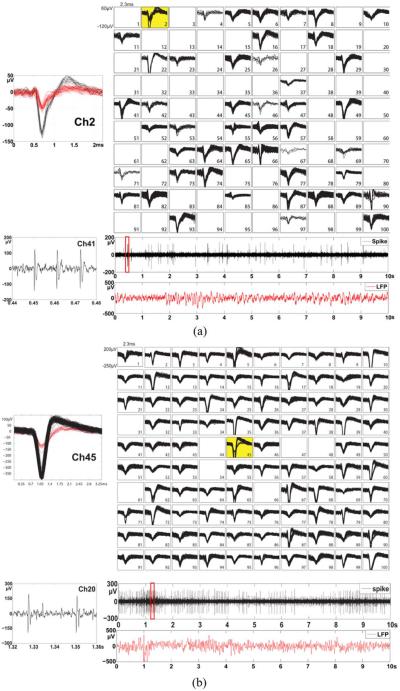
Fig. 16.
(a) Simultaneously recorded in vivo neural spikes from an awake Yorkshire swine and (b) a rhesus macaque monkey using the 100-Channel fully implanted wireless neurosensing device. The 100-channel sorted neural spikes are displayed in a 10 × 10 grid showing in the top column of the figure. The insets at the top left corner of each grid show examples of the channel that has multiple units. The bottom column of the figure shows the spike signal and LFP signal extracted from a signal channel. The insets on the left of each LFP trace show the zoom-in view of the spikes.

