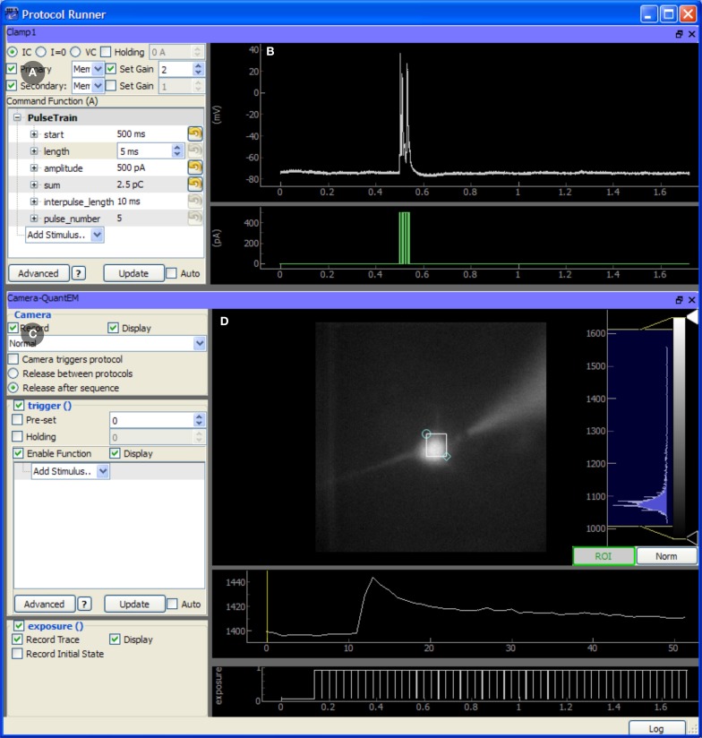
Figure 4.
Screen capture of the TaskRunner module running a calcium imaging task during recordings from an mouse auditory cortex neuron in a brain slice experiment. The acquisition system is described in Figure 3. The cortical neuron is filled with the calcium indicator Fluo-4 (200 micromolar) and is electrically stimulated through the patch pipette. Additional control panels for selecting devices, running protocol sequences, and configuring the data acquisition board are hidden. To design this task, the experimenter has already selected the camera and patch-clamp channel to be included, and has rearranged the panels to optimize use of the window space. The task has been executed once, and the results are displayed in the rightmost panels. (A) Control panel for configuring the behavior of the patch clamp amplifier, including the output waveform specification. (B) Plot showing the most recent electrode recording and the command waveform. (C) Interface for controlling the Camera. This includes control over the camera's frame transfer mode and triggering waveform. (D) The recorded video data is displayed and a region of interest defines the pixels that are averaged together and plotted in the traces below, showing the calcium transient evoked by action potentials in the cell. The bottom-most plot shows the exposure times of acquired camera frames for reference to the electrical recording.

