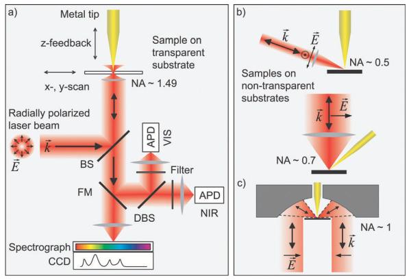
Fig. 6.
(a) Schematic of an experimental setup employing on-axis illumination of a transparent sample used to observe simultaneous Raman scattering and photoluminescence of carbon nanotubes.21 A sharp metal tip is positioned in a tightly focused radially polarized laser beam. The optical signal is detected either by two avalanche photodiodes (APDs) for the VIS and NIR spectral range or by a combination of a spectrograph and a CCD. (b) Side-illumination of the tip on top of a non-transparent substrate. (c) Focusing of light using a parabolic mirror with high numerical aperture. To generate a strong field component parallel to the tip axis required for efficient field enhancement, scheme (a) and (c) utilize a radially polarized laser mode.97-99

