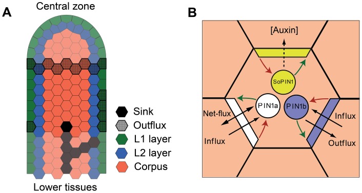
Figure 4. Basic features of the proposed model of polar auxin transport.
(A) The layout of cells in the tissue model used to simulate convergence point and vascular strand patterning. Cells in the L1 are colored green, those in the L2 blue, and corpus cells are colored red. Cells assumed to export auxin outside the explicitly modeled part of the shoot are stippled. In addition, a sink is located at the base of the tissue (black cell). Faded cells represent parts of the tissue outside the scope of the model. (B) Schematic view of a cell and its neighbors that illustrates the factors determining PIN allocation to segments of the cell membrane. PIN1a is shown in white, PIN1b in blue and SoPIN1 in yellow. Exocytosis is represented by green arrows, endocytosis by red arrows.

