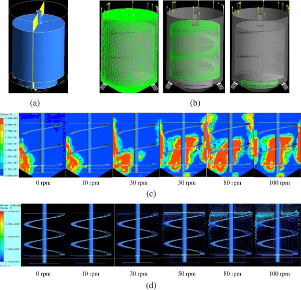
Figure 3.
CFD modeling of steam holdup and solids flow in the helically agitated pretreatment reactor. (a) The reactor diagram in which the flow regime of the cross-section was simulated in the CFD calculation. (b) Geometric structure of the reactor in the CFD model. Left, mesh cells and structure; middle, motion region of the helical ribbon impeller; and right, motion region of the bottom anchor stirrer. (c) Conservative gas volume fraction under different agitation rates. (d) Fluid velocity distribution at different agitation rates. In this modeling, pretreated CS materials were assumed to the high viscose liquid with high apparent viscosity of 2.31 Pa · s; the hot steam stream was assumed to be inert air with a flow rate of 1.75 m/s. CFD, computational fluid dynamics; CS, corn stover.

