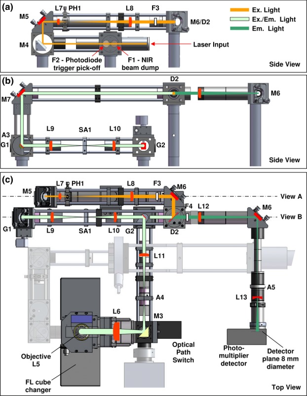
Figure 3.

Schematic diagram of the laser scanning beam path (see text for description). L, lens; F, filter; PH, pinhole; A, aperture; SA, slit aperture; D, dichroic mirror; G, galvanometer. (a) Cut-away side view showing the laser beam conditioning optics at the back of the system. (b) View showing a cut-away side view of the beam scanning optics. (c) Top view of the whole system combining the optics from views (a) and (b) with the rest of the system including the photomultiplier arm.
