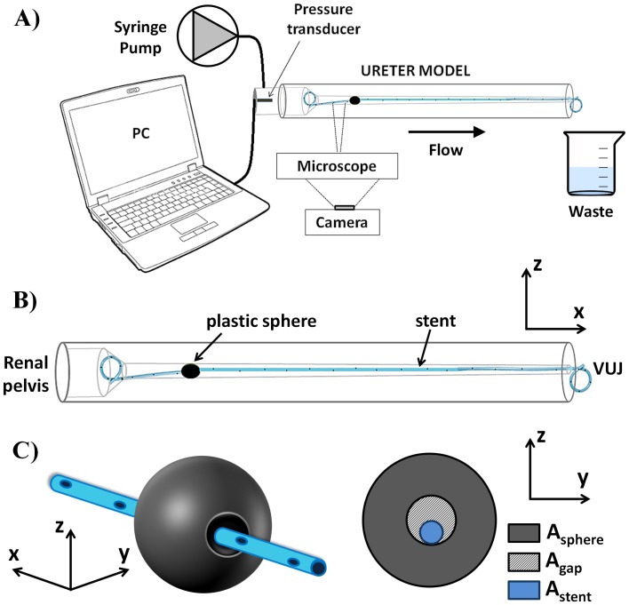
Figure 2. Experimental setup.
A) Syringe pump and pressure transducer were connected to the renal pelvis compartment of the ureter model. A microscope and a CCD camera were used for flow visualisation experiments. B) Schematic of the ureter model. The stent was inserted within UM, with its curling ends positioned in the renal pelvis and bladder compartment. C) A plastic sphere was used as a model of ureteric obstruction, with the stent passing through its hole so that the severity of ureteric obstruction (OB%) could be quantified from Eq. 1.

