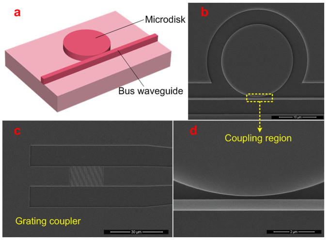
Figure 3. MDR design.
(a) schematic figure of the MDR composed of a disk and a bus waveguide (vertical grating couplers not shown); (b) SEM image of the fabricated MDR, the scale bar represents 10 μm; (c) SEM image of the vertical grating coupler, the scale bar represents 30 μm; (d) SEM image of the zoom-in coupling region between the disk and the straight waveguide, the scale bar represents 2 μm.

