
Figure 5. Schematic of the experimental setup.
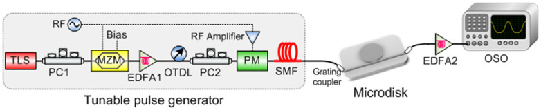
First, a continuous wave beam is emitted by a tunable laser source and is then modulated into Gaussian-like pulses by the tunable pulse generator module. Subsequently, the signal is coupled into the MDR by the designed grating coupler. Finally, the MDR output is amplified and observed. TLS: tunable laser source. PC: polarization controller. RF: radio frequency. MZM: Mach-Zehnder modulator. EDFA: erbium doped fiber amplifier. OTDL: optical tunable delay line. PM: phase modulator. SMF: single mode fiber. OSO: optical sampling oscilloscope.