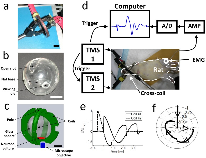
Figure 2. Cross coil experiments.
a) A photograph of the cross coil used in the experiment. The two coils interlock on perpendicular planes and connect to two independent stimulators. b) A photograph of the glass sphere that was custom made to fit inside the cross coil. The glass coverslip, on which the neuronal culture grows, and the fluid medium were inserted through a slot located at the top of the sphere. The coverslip lay on a flattened base at the bottom of the sphere and was observed via a viewing aperture, which was sealed with optically transparent glass. See also Video S1. c) Schematic of the setup – the coverslip (red) was placed in a glass sphere inside the cross coil while an inverted epi-fluorescence microscope monitored neuronal activity. Scale bars in a–c are 2 cm. d) Cross coil setup for rat experiments. The rat's head was positioned inside the cross coil (in place of the glass sphere, which was not used). EMG electrodes recorded muscle potentials from the Gastrocnemius. The EMG data was digitized and synchronized with the rfTMS pulses to assess the motor response to rfTMS. e) The induced electric field in the cross coil was measured using a pick-up coil oriented first on the plane of one of the coils (solid line) and then on the plane of the second coil (dashed line). The Magstim stimulator was loaded to 100% and the HMS was loaded with 3.5 kV (see details in the Methods section). f) A reconstruction of the effective electric field created from the sum of the two perpendicular components measured in e) with the field of coil #1 directed along the x-axis and the field of coil #2 along the y-axis. The effective field was reconstructed for a specific location just inside the poles of the cross coil (‘Neuronal culture’ arrow in Figure 2d). The effective field completes ¾ of a spiral cycle during the magnetic pulses cycle, as indicated by the black arrows.

