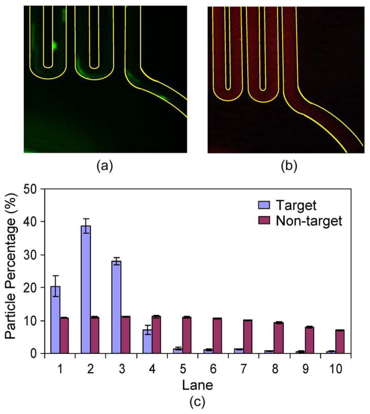
Fig. 6.
Distributions of target and nontarget particles across the channel width at the end of the TART incubator. A permanent magnet was placed to the left of the incubator channel. (a) and (b) Fluorescent micrographs of target and nontarget particles, respectively, at the end of the incubator. (c) Percentage distributions of target and nontarget particles across the channel width at the end of the incubator.

