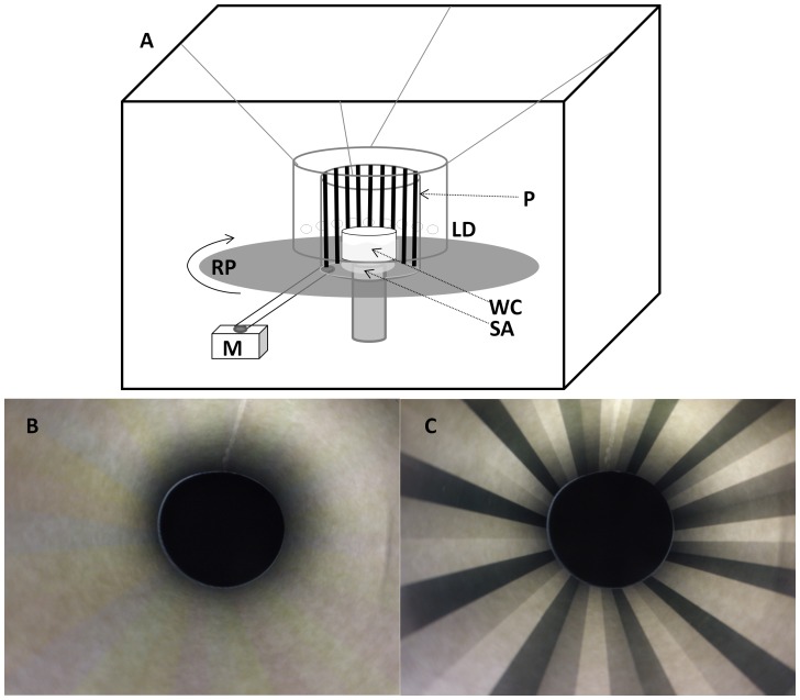
Figure 1. The optomotor apparatus.
(A) The optomotor consisting of: a water container (WC), a stationary arena (SA), a rotating platform (RP), an electric motor (M), an experimental pattern (P), light emitting diodes- LEDs (LD). (B) The polarized experimental pattern photographed from the stationary arena looking upwards, (C) same image as B, but viewed through a polarizing filter.

