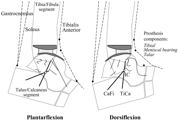
Figure 12.
Diagram for sagittal mobility with the BOX ankle. Diagram for sagittal mobility of an ankle replaced with the BOX prosthesis. The geometrical arrangement of the passive structures are shown at the extremes of the flexion arc: in maximum plantarflexion (left), and maximum dorsiflexion (right). The kinematics is guided by the isometric rotation of the CaFi and TiCa ligaments (solid bold). The articular surfaces (the arcs in nearly contact), the other ankle ligaments (buckled segments), and the instantaneous centre of rotation IC (empty circle) are also depicted. With respect to Figures 1 and 2, the course of the three main muscle-tendon units and the pulleys (full circles) representing the extensor retinaculum bands for force redirection are also depicted. The bi-concave meniscal bearing (dots area, in between) is required to slide forwards on both components during dorsiflexion and backwards during plantarflexion so that the bones roll as well as slide upon each other. During this motion backward and forward, full congruity is maintained at the two articulating surfaces. The rolling element of the relative motion is manifested by the sliding of the bearing on the tibial component. The axis of dorsi-plantarflexion passes through IC and moves forwards and proximally during dorsiflexion, backwards and distally during plantarflexion.

