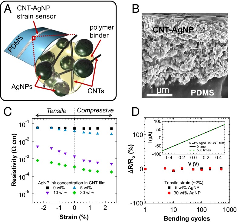
Fig. 1.
CNT-AgNP composite films. (A) Schematic of a CNT–AgNP composite film patterned on a PDMS substrate. (B) Cross-sectional SEM image of a CNT–AgNP composite film on PDMS showing that CNTs are tangled in between AgNPs and polymer binders. (C) Resistivity as a function of strain for CNT–AgNP composites with different AgNP concentrations. (D) Resistance change (ΔR/Ro) as a function of bending cycle (∼2% strain) for 5 and 30 wt % AgNP. Inset shows the current–voltage characteristics before and after 500 cycles.

