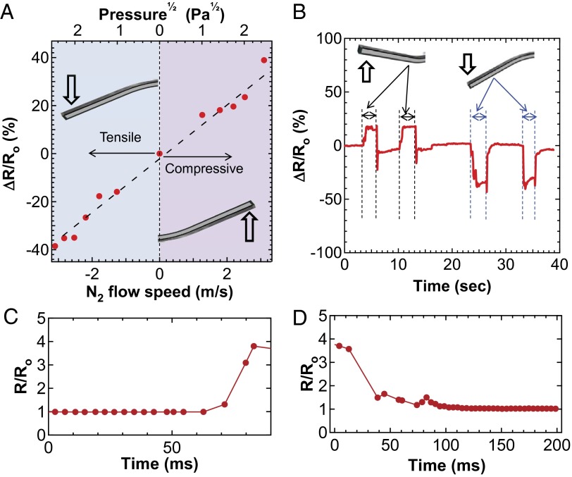
Fig. 3.
Electrical characterization of e-whiskers. (A) The ΔR/Ro as a function of compressive and tensile stress induced by gas flow for a representative whisker, where ΔR = R0 − R. The bottom x axis displays the gas-flow velocity used to induce displacement and the top x axis displays the corresponding pressure. (B) Time-resolved resistance change by displacing a whisker upward and downward (∼2 mm displacement) by applied pressure. (C, D) Response time of a whisker when bent downward and relaxed, respectively.

