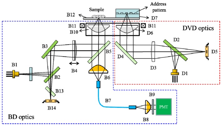
Fig. 1.
Schematic view of the optical structure of the BSM. For the DVD optics, light from a red laser diode (D1) is reflected by a beam splitter (D2) and collimated by a collimator lens (D3). The beam is then reflected by a fold mirror (D4), penetrates the objective lens (D6, NA 0.6), and is focused onto the Al-coated address pattern deposited on the protection layer (D7). The address signal is reflected from the patterned Al layer, transmitted through D2, and detected by the photodiode (D5). For the BD optics, light from a blue laser diode (B1) passes through a glass plate and is then successively reflected by beam splitters (B2 and B3). The laser beam is then collimated by the collimator lens (B4) and reflected by the dichroic mirror (B5). Finally, the beam penetrates the objective lens (B10, NA 0.85) and is focused onto the sample on the cover glass (B12). The blue laser beam reflected from the sample slide is collimated by collimator (B10) and reflected by B5 and B3, then passes through astigmatic plate (B13), and is finally focused onto the photo detector (B14). The emission fluorescence signal is collimated by B10, transmitted through B5, and coupled onto a multimode fiber (B7). The fluorescence signal then passes through B7 and is collimated by a collimator lens (B8); it is then transmitted through a narrow-band emission filter (B9) and impinges on the PMT.

