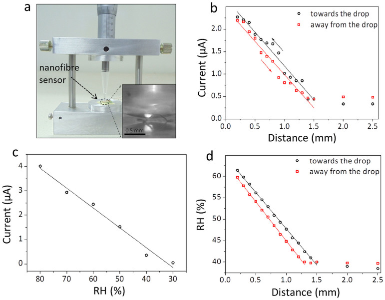
Figure 6. RH above a water drop.
(a) A photograph of the setup used for the study. It consists of a plastic tip carrying the tiny water drop which can be moved in vertical direction using a screw gauge arm. Inset is the magnified image when the water drop is very close to the sensor. Reflection of the drop is seen from the device surface. (b) Variation in the current (at 1 V), as the water drop is brought towards and taken away from the nanofibre sensor. (c) Variation of current through the nanofibres at different RH measured at 1 V. (d) Derived plot of variation of RH of water drop with distance.

