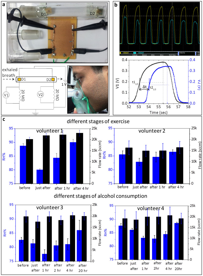
Figure 8. Integration of two humidity sensors for simultaneous measurement of humidity and flow of the exhaled human breath.
(a) A photograph of the humidity cum flow sensor is shown in top. It has two supramolecular humidity sensors, D1 and D2, placed apart at a distance of 8 cm inside a glass tube of inner diameter 21 mm. The circuit diagram of the experimental set up is shown below (left). Two devices are connected in parallel and applied a bias of 1 V. Two resistors (20 MΩ each) are connected in series with the devices to give out voltage signals to an oscilloscope. A photograph of a volunteer performing breathing trial (below, right). A commercially available breathing mask was used to carry the exhaled breath over D1 and D2 sensors. After every breath out, the stray humidity in the glass tube was driven away by flushing with dry N2 for a second while the volunteer inhaled. (b) Simultaneous humidity and flow sensing from the integrated device. The screen image of oscilloscope output of exhaled breath from a healthy individual (top). Below is a single breathing cycle showing calculation of ‘Δt’, the time difference between the two sensors to reach half of the peak value. (c) Demonstration of integrated device for human breath applications. Histogram plots showing variation of humidity and flow in the exhaled breath by exercise induced dehydration at different stages and by alcohol induced dehydration before and after alcohol consumption.

