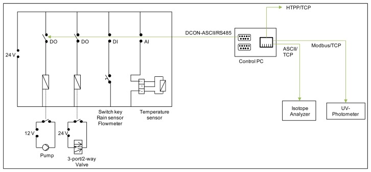
Figure 5.
Schematic circuit diagram of the switch cabinet including analogue input, digital in- and output cards with connections to pumps, valves, push button, rain sensor, flowmeter and temperature sensors as well as a connection to the control PC and connections from the control PC to the analytical equipment and the internet.

