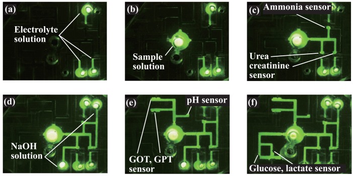
Figure 8.

Transport of a fluorescein solution in the network of flow channels. (a) Solutions for the ammonia, urea, and creatinine sensors were injected and filled in the sensing area. (b) Another solution was filled in the sample injection port. (c) The solution was transported to the respective sensing areas of ammonia, urea, and creatinine. (d) NaOH solutions were mixed. (e) The solution was transported to the sensing area of GOT and GPT. (f) The solution was filled in the glucose- and lactate-sensing areas.
