Figure 2.
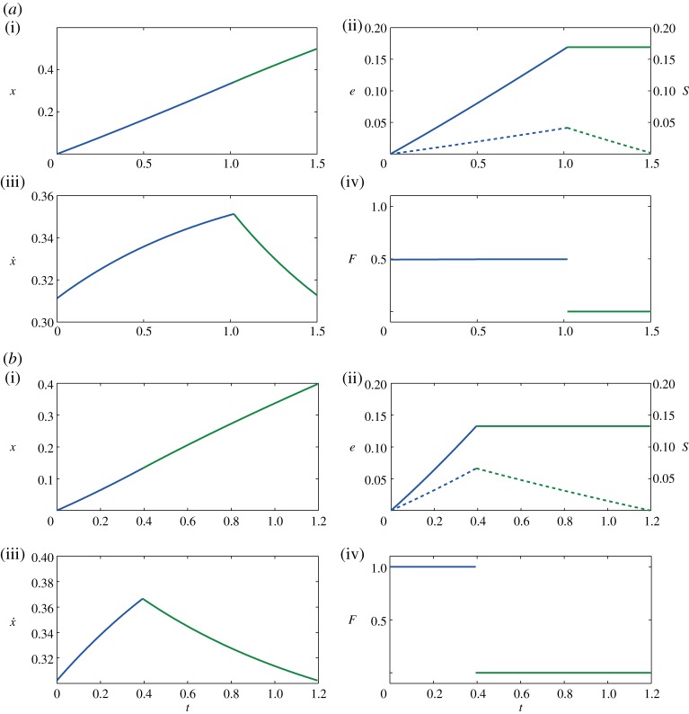
Optimal trajectories showing (i) displacement x, (ii) energy spent e (solid) and stored S (dashed), (iii) velocity  and (iv) thrust force F. These trajectories have been obtained by maximizing (2.11) under the constraints (2.5)–(2.10) with β=0.75, γ=0.25 and
  . The solution shown in (a) is obtained for F*=0.5 and the total distance x(tf)=0.5 is reached in tf=1.5 using a total energy e(tf)=0.17. The performance index J=3 and the control duty cycle ta/tf=67%. The solution reported in (b) is obtained for F*=1 and the total distance x(tf)=0.4 is reached in tf=1.2 using a total energy e(tf)=0.13. The performance index is still J=3 and the control duty cycle ta/tf=33%. (Online version in colour.)

