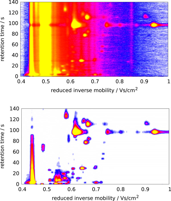
Figure 2.
IMSC visualized before and after preprocessing.Top: Heat map of a raw IMSC. X-axis: reduced inverse mobility t in Vs/cm2; Y-axis: retention time r in seconds; signal: white (lowest) < blue < purple < red < yellow (highest), reactant ion peak (RIP) at t = 0.48Vs/cm2. Bottom: IMSC after preprocessing using bc-dn-s (see text).

