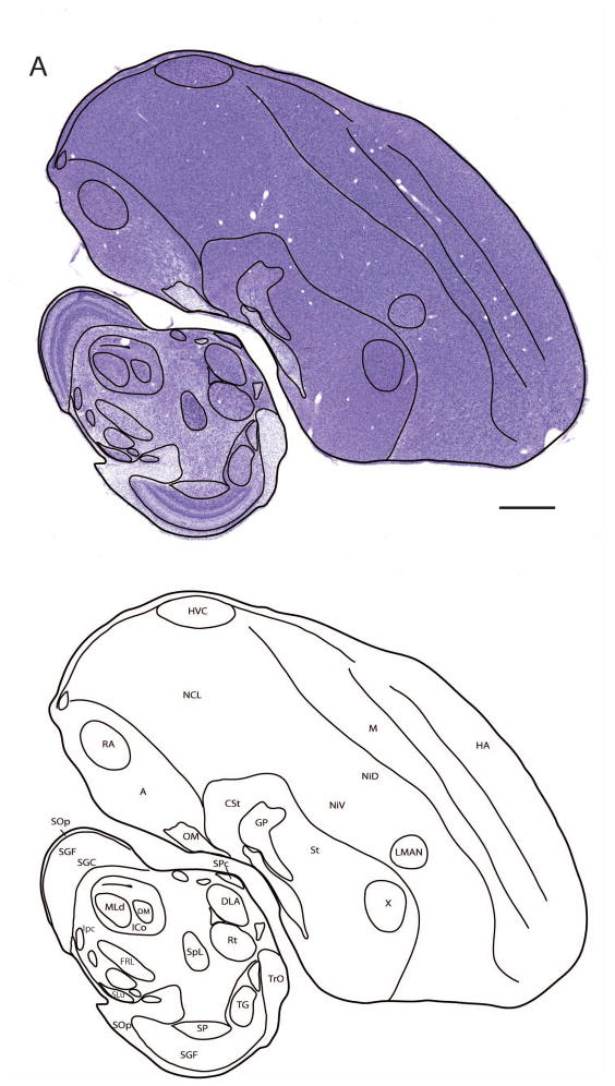
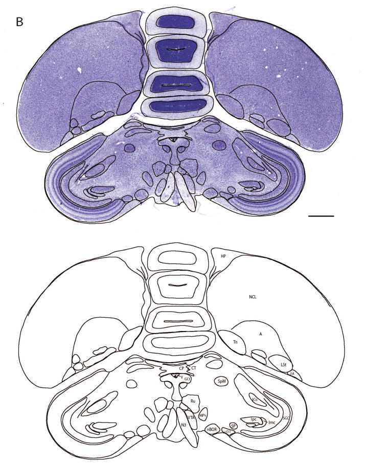
Figure 7. Drawing and annotation of representative Nissl-stained sections in sagittal and transverse planes.
(A and B) Overlays of line drawings superimposed over Nissl-stained images of a zebra finch brain sections taken from the sagittal (A) and transverse or “Frankfurt” planes of section (B). Image in A is a sagittal section ~2.2 mm from the midline that includes HVC and RA. The line drawings are presented without the Nissl-stained images in the panels immediately beneath panels A and B. Only brain structures and cell groups that can be defined by cytoarchitectonic features in Nissl are drawn to illustrate how the brain sections can be parcellated. Structures defined by myeloarchitectonic features (e.g. fiber fields, commissures) are not shown. A subset of identified anatomical structures are indicated on the figure; for abbreviations, see list. Scale bar = 1 mm.


