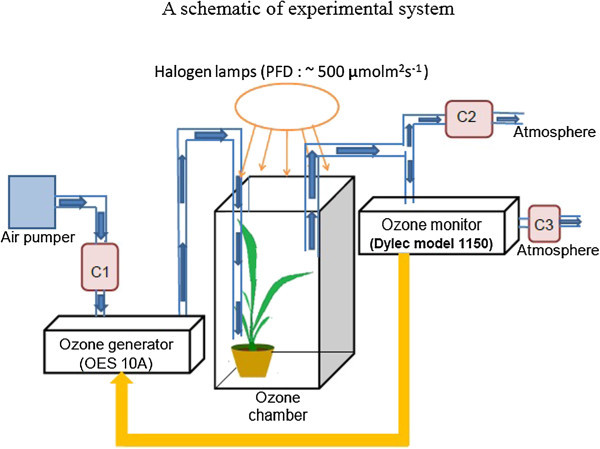
Figure 7.

A schematic of experimental system. A schematic of experimental system for introducing Charcoal filtered air (CF air) and O3. Signal from the O3 monitor was fed back to the O3 generator to control precisely the concentration of O3 inside the chamber. Charcoal filter C1 was used to remove the ambient O3 in the environment. C2 and C3 were used to remove all O3 before releasing the air into the room. Flow rate was 10 l/min. Three halogen lamps with fiber optic light guides were used to provide light intensities of 500 μmolm-2 s-1 from the top of O3 chamber (not shown explicitly).
