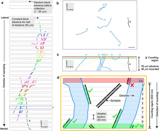
Fig. 1.

Overview of sampling and synapse counting procedures. a The brain is sectioned in the parasagittal plane, lateral to medial. Before collection, the cutting stage is advanced a random distance (1–50 μm). The dendrites of the labeled neuron are shown in different colors in each section. Synapses formed with dendrites are counted in a counting region of fixed height located at the top surface of each section (shown in c and d for blue-outlined section marked with the asterisk). The axon (a) is shown in black. b Enlarged view of blue-outlined section in (a) rotated orthogonally to show dendritic and axonal (a) fragments that were digitally traced at high magnification. Fragments ending at the top surface of the section (‘high endings’; H) correspond to the location of the counting region. c Enlarged view of blue-outlined section in (a), (same orientation to (a), but orthogonal to b). Putative synapses (not shown) made with the high endings (H) of dendritic fragments are counted within a counting region of 500 nm height, on the top of the 46 μm-thick mounted section. d Orange box in c, expanded for two dendrites, with a representation of the procedure for counting of synapses on dendritic fragments. The counting region consists of ten ultrathin serial sections (numbered 1–10), each cut with a block advance of 50 nm. A look up (l.u.) section (Sterio 1984; Howard and Reed 1998) is located above the counting region (red shade). Synapses in gray represent those not formed with labeled dendrites. Synapses in green represent those formed with labeled dendrites that are counted (green ticks) according to stereological counting rules. Synapse in red is formed with a labeled dendrite but is not counted (red cross) because its top is not within the counting region (see “Materials and methods”)
