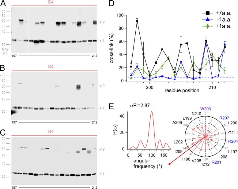
Figure 5.
Cross-linking analysis of the mutants by Western blot. (A–C) Representative images of the Western blot analysis for the S4 segment of the +7-A.A. mutant (A), the −1-A.A. mutant (B), and the +1-A.A. mutant (C). White line in A indicate that intervening lanes have been spliced out. (D) Accumulated data of the cross-linking analysis for the linker mutant channels. The data were plotted as the mean ± SEM (n = 3). (E) The power spectrum of the Fourier transform of the data (197–212) and the helical wheel diagrams for the +7-A.A. mutant. The sum vector (deep red) indicated points the same direction to that of WT shown in Fig. 3 D.

