
Fig. 3.
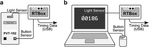
Diagrams of the connection between the RTbox and the device being tested. (A) For the PVT-192, a light sensor was attached from the RTbox to its light-emitting-diode dot-matrix display, and a button sensor was attached from the RTbox to the response button so that both would be triggered at exactly the same time. Events from the two sensors were time-stamped by the RTbox and transmitted via a USB cable to another PC. (B) Similar connections were established in order to characterize the PC-PVT. Reaction times recorded by each device were compared with those derived from the RTbox time stamps