Abstract
The unique biomechanical properties of native tissue are governed by the organization and composition of integrated collagen and elastin networks. We report an approach for fabricating spatially aligned, fiber-reinforced composites (FRC) with adjustable collagen fiber dimensions, layouts, and distribution within an elastin-like protein matrix yielding a biocomposite with controllable mechanical responses. Microtransfer molding is employed for the fabrication of hollow and solid collagen fibers with straight or crimped fiber geometries. Collagen fibers (width: 2 – 50 μm, thickness: 300 nm – 3 μm) exhibit a Young’s modulus of 126 ± 61 MPa and an ultimate tensile strength (UTS) of 7 ± 3.2 MPa. As fiber networks within composite structures, straight fiber layouts display orthotropic responses with Young’s modulus ranging from 0.95 ± 0.35 to 10.4 ± 0.5 MPa and tensile strength from 0.22 ± 0.08 to 0.87 ± 0.5 MPa with increasing fraction of collagen fibers (1–10% v/v). In contrast, composites based on crimped fiber layouts exhibit strain-dependent stiffness with an increase in Young’s modulus from 0.7 ± 0.14 MPa to 3.15 ± 0.49 MPa, at a specific transition strain. Through controlling the microstructure of engineered collagen fiber networks, a facile means has been established to control macroscale mechanical responses of composite protein-based materials.
Keywords: Collagen microfibers, elastin-mimetic protein polymer, Bio-MEMS, fiber reinforced composite, tissue engineering, MEMS
1. Introduction
Collagen fiber networks and elastin are the primary architectural elements in nearly all forms of tissue. These extracellular components dictate both a biological and mechanical microenvironment for normal cell function, as well as bear and transmit loads as encountered by the tissue. While collagen provides strength and mechanical integrity, elastin is responsible for resilience and tissue compliance and both are critical components for shape and energy recovery when tissue structures are subjected to deformation loading. Indeed, in many tissues collagen fibers may be crimped, which allows the more resilient intervening elastomeric matrix to sustain repetitive small loading forces, while reserving the stronger collagen fiber network, as the principle load-bearing element in response to high strain deformation.[1] All told, the geometry and 3-dimensional spatial layout of collagen fiber networks has a profound influence on tissue biomechanical properties, as well as associated cell behavior. Despite our recognition of these important design features, biofabrication strategies to generate and assemble collagen fiber networks either alone or in association with elastin-mimetic protein polymers remain limited. The development of such approaches will be a necessary step for the engineering of robust artificial living tissues with well-defined mechanical and biological properties.
Similar to other approaches described for the production of microscale polymeric fibers, conventional approaches which have been described for the fabrication of collagen microfibers include electrospinning [2]–[5] and wet-spinning. [6][12] Electrospun fibrous composite materials produced from aqueous mixtures of collagen and elastin and blends of collagen and elastin with other polymers, such as polydioxanone and poly(lactic-co-glycolic acid) (PLGA) have been reported. [13]–[16] However, collagen fibril self-assembly, as indicated by the presence of D-periodic banding, is not typically observed using these approaches. [17] Fiber reinforced composite materials constructed from wet-spun collagen fibers within an elastin-mimetic matrix have been demonstrated. The ability to modulate mechanical properties of such composites has been demonstrated by varying fiber organization[18] and through the induction of defined fiber crimp.[19] But the fiber diameters (25–200 μm) obtained by wet spinning are relatively large as compared to that observed in native tissue. Moreover, varying the geometric or organizational features of dense fiber arrays involves highly controlled manual techniques. In general, extrusion-based approaches for fiber production are limited in their ability to precisely control fiber shape, dimension, spatial layouts, and packing densities.
MEMS processing technology offers the size scale and resolution necessary to mimic native tissue architectures and also the ability to create organized 2-dimensional (2D) and 3-dimensional (3D) structures. Consequently, micropatterning approaches have been utilized for controlling the spatial organization and surface topology of tissue scaffolds. While synthetic material scaffolds have been developed using MEMS patterning approaches, such as microsterolithography, [20] optical lithography, [21] and laser micromachining, [22] micromolding offers the most benign processing approach for naturally derived materials.[23]–[24]
This report presents the development of a MEMS-based micromolding approach suitable for the fabrication of microfibers and fiber-reinforced composites by reconstituting monomeric collagen as microfibers within an elastin-mimetic protein polymer matrix. It was postulated that the use of microfabrication processes to sculpt and demold collagen would produce fibers on dimensional scales similar to those observed in native tissues and with controllable in-plane and out-of-plane geometries obviating any manual handling of fibers to induce crimped structure. In this manner, a laminated 3D framework could be used for engineering synthetic tissue with adjustable mechanical characteristics.
2. Results and discussion
2.1. Fabrication of spatially designed collagen fiber reinforced elastin-like protein polymer composites
The molding-based fabrication approach for collagen type I microfibers has been briefly described in an earlier report.[25] Figure 1 illustrates the fabrication process for in-plane fiber networks. For in-plane fibers, trenches with the designed fiber network layouts were defined by photolithography on a silicon wafer and etched into the silicon wafer using inductively coupled plasma (ICP) etching. A thin film (600 – 800 nm) of parylene was deposited on the template to facilitate subsequent collagen fiber release. A conformal collagen film from solubilized collagen in 10 mM HCl was solvent cast onto the template. Collagen fibrillogenesis was triggered by neutralizing the solvent cast collagen film with a buffer solution at 37°C. The resultant collagen film was crosslinked in vapor phase glutaraldehyde. A thin layer of water-soluble polymer, polyvinyl pyrrolidone (PVP), was solvent cast onto the collagen film. The PVP film served to protect discrete regions of collagen during the subsequent etching process. It also provided rigidity to the material being etched, preventing delamination of the collagen film during processing. A combination of dry mechanical polishing and oxygen plasma reactive ion etching (RIE) was utilized to partially etch PVP and collagen, consequently yielding individual collagen microfibers in the trenches. To facilitate removal of fiber networks, a second layer of PVP was cast. Water-soluble tape (1stMaskingTape Inc., Torrance, CA) was used to demold the collagen fiber network.
Figure 1. Fabrication process for in-plane collagen fiber networks.
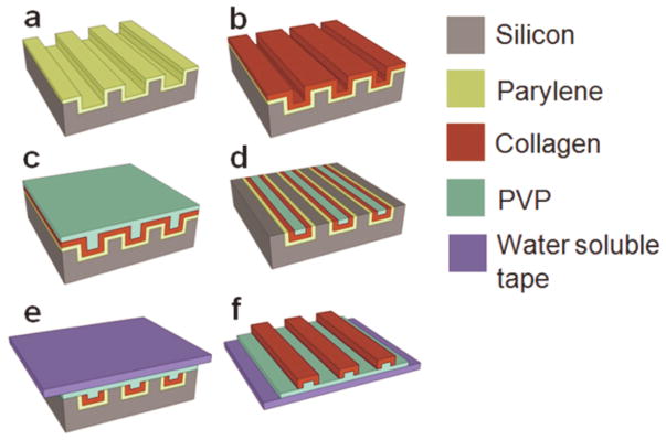
(a) Parylene release layer deposition on a silicon template. (b) Collagen film solvent casting, neutralization, and cross-linking. (c) PVP mask layer solvent casting. (d) Collagen fiber individualization using mechanical polishing and RIE. (e) PVP film casting and water-soluble tape application for fiber network extraction. (f) In-plane collagen fiber network on a water-soluble film.
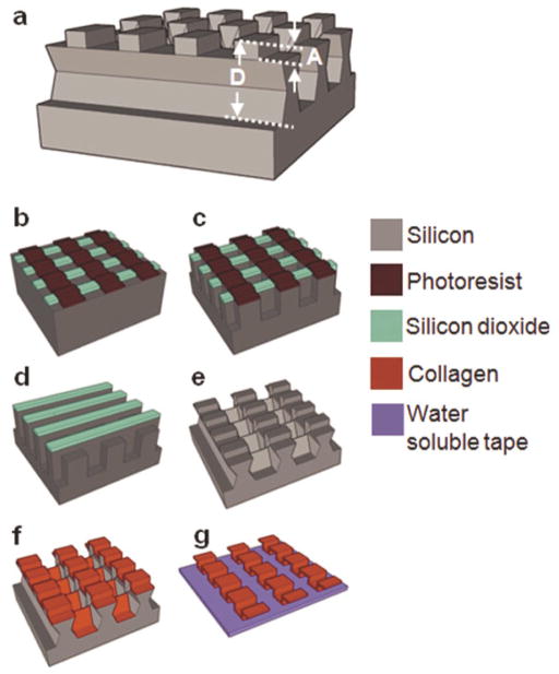
Silicon templates for the fabrication of out-of-plane crimped fibers were constructed to have a multi-depth structure necessary for delineating out-of-plane geometries (Fig. 2a). Sequential ICP and potassium hydroxide (KOH) etching steps were used to achieve this (Fig. 2b–g). A 1 μm thick silicon dioxide (SiO2) layer was thermally grown on a silicon wafer. Photolithography and ICP etching of SiO2 were then used to define straight patterns in the SiO2 layer. Straight photoresist patterns were defined perpendicular to the SiO2 straight patterns and ICP etching used to etch silicon to obtain a depth equal to the differential of the total depth, D, and two times the crimp amplitude, A. The photoresist layer was then etched using acetone and RIE. ICP etching was then performed to further etch the desired depth of A. The silicon template was immersed in a KOH bath to etch bridges between the structures that define the fibers and create slightly reentrant silicon trench sidewalls. Sequential spray coating was used to cast collagen onto the template. The multi-depth templates designed for out-of-plane crimped fibers prevented collagen from depositing on the reentrant sidewalls, forming undulated fibers pre-separated from one another. The individual fiber network was then transferred to a water-soluble tape.
Figure 2. Fabrication process for out-of-plane crimped collagen fiber networks.
(a) Silicon dioxide and photoresist patterning on a silicon wafer. (b) ICP etching of silicon. (c) Photoresist removal and ICP etching. (d) KOH etching of silicon for etching the bridges yielding a reentrant multi-depth template. (e) Collagen spray coating. (d) Out-of-plane crimped collagen microfiber network on a water-soluble tape.
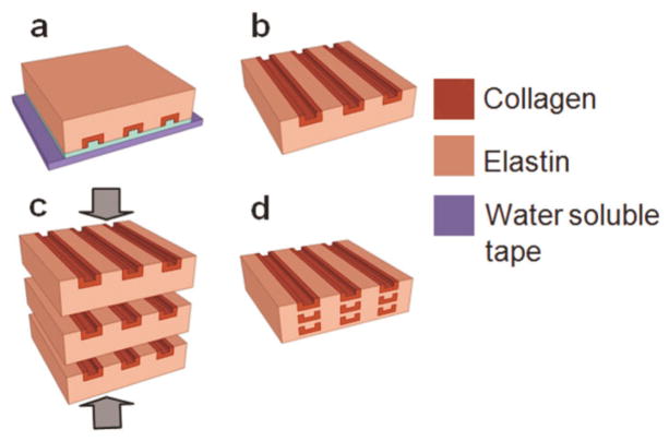
In-plane collagen fiber networks were transferred to an elastin-like protein polymer matrix, LysB10, which exhibited a distinctive sol-gel transition temperature at 13°C in water (Fig. 3).[26] A film of elastin-like protein polymer was cast onto the water-soluble film securing the collagen fiber network. The processing was carried out at 4 °C using an elastin solution that gelled at 37°C. The water-soluble film was dissolved in water, leaving behind collagen fibers embedded in the elastin-like protein polymer matrix. A single lamellar sheet of the fiber composite was designed to be 100 μm thick in the hydrated state with the aid of plastic spacers. Fiber delamination and entanglement were observed during the elastin casting process when using networks of independent fibers. Entanglement could be prevented by designing collagen fiber networks with periodic interconnecting bridges (periodicity: 250, 500 μm). Multi-lamellar composites were fabricated by stacking and incubating desired number of individual sheets at 4°C for 17 h to liquefy and fuse the elastin-like matrix, which were compressed to a final film thickness of 100 μm using plastic spacers, and then crosslinked in a 0.5% glutaraldehyde solution. Glutaraldehyde, although a very common crosslinking agent for collagen, has reported drawbacks of cytotoxicity and poor biocompatibility and may generate an untoward inflammatory response. [28] [29][30] Post-treatment approaches and alternate crosslinking methods continue to be explored as a means of improving biological responses to crosslinked materials.[31]
Figure 3. Fabrication process for collagen-fiber reinforced elastin-mimetic composite tissue scaffolds.
(a) Casting on collagen microfiber network of an elastin-like protein polymer solution. (b) Water soluble tape and PVP dissolution yielding a fiber reinforced elastin composite lamellar sheet. (c) Lamination of multiple fiber reinforced elastin-like protein sheets. (d) Multilamellar sheet fusion and compression at 4°C.
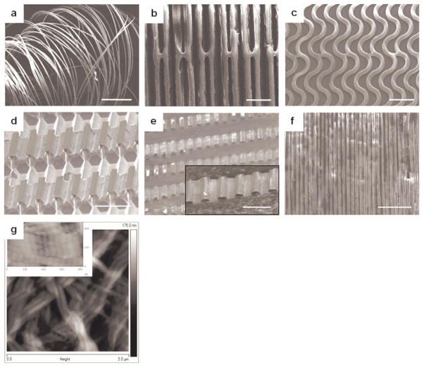
The spatial layouts of the collagen microfiber networks could be controlled using appropriate silicon template designs with desired geometries in the horizontal and vertical planes. Layouts included unidirectional straight, in-plane crimped, and out-of-plane crimped fibers (Fig. 4a–e). Fine control over fiber dimensions, packing densities, and layouts could be obtained through this approach with the amplitude and wavelength of crimped fibers defined by template design. This scheme was used to fabricate fibers with widths spanning from 2 μm (length: 2 cm) to 50 μm (length: 4 cm), and fiber thicknesses varying from 300 nm to 3 μm. The finest fiber achieved using this process was 2 μm in width with a thickness of 300 nm (Fig. 4f). The conditions in this fabrication approach promoted self-assembly of collagen monomers into fibrils with a D-periodic banding of 68 ± 3 nm, as measured by AFM, consistent with native collagen (Fig. 4g).[32]
Figure 4.
(a) Unsupported individual microfibers after water-soluble film dissolution (scale bar 1 mm). (b) Spatially designed unidirectional straight collagen microfibers (scale bar 50 μm). (c) In-plane crimped microfibers (scale bar 100 μm). Fiber alignment in (b) and (c) is maintained using bridges connecting the fibers. (d, e) A multi-depth silicon template and corresponding out-of-plane crimped microfibers (scale bars 50 μm). (f) A collagen nanofiber network (fiber width: 2 μm and thickness: 300 nm) demonstrating the dimensional scalability of this strategy (scale bar 25 μm). (g) An AFM image illustrating the fibrillar structure and D-periodic banding (inset image) of the developed collagen microfibers.
Fiber dimensions and shapes were controlled by template design and properties of the collagen solution. In particular, for a given template, fiber wall thickness was a function of the concentration and volume of the collagen solution, where thickness could be approximated by the equation (1).
| (1) |
where Td = dry cast film thickness, Tw = wet film thickness, M = % of solid collagen in the solution, V = collagen solution volume, S = effective surface area of the template used for solvent casting, C = collagen concentration, and ρ= collagen density.
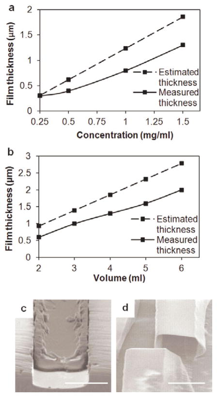
Measured fiber wall thickness values followed the same trend as the estimated values with differences arising from loss of the solution to the base of the template (Fig. 5a). Hollow or solid fibers could be obtained by regulating the depth of the template and collagen solution properties (Fig. 5b–c). Solid ribbon-like fibers were fabricated by casting collagen films to fill shallow trenches (< 6 μm), while the deposition of a thin conformal collagen film yielded hollow fibers.
Figure 5.
Variation of the fiber wall thickness with (a) collagen solution concentration at a volume of 4 mL and (b) volume of the collagen solution at a concentration of 1.5 mg/mL. (c) A ribbon-like solid fiber fabricated using a 4 μm deep template (volume: 5 mL, concentration: 2 mg/mL). (d) A hollow microfiber lumen fabricated using a 20 μm deep template (volume: 3 mL, concentration: 1.5 mg/mL) (scale bars 20 μm).
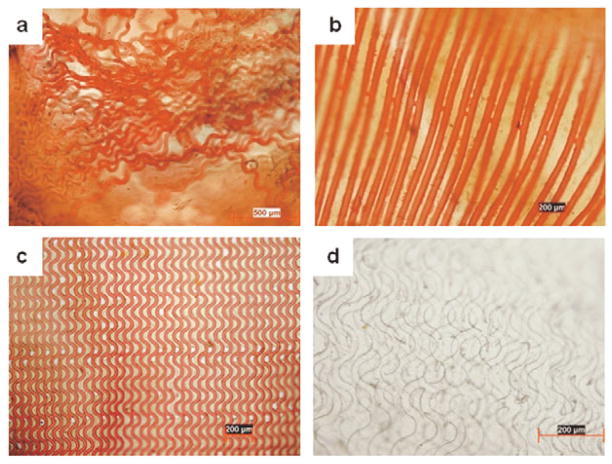
Fiber reinforced lamellae with straight and in-plane crimped collagen fibers embedded in an elastin-like matrix could be produced.. Loss of fiber alignment (Fig. 6a) could be prevented through bridges between the patterned fibers (Fig. 6b–c) The fiber volume fraction could be enhanced by creation of multilammelar constructs with the final structure compressed to 100 μm thickness (Fig. 6d).
Figure 6.
Collagen-fiber reinforced elastin-mimetic composites. Collagen fibers were selectively stained red using Van Gieson’s. (a) Fiber networks with independent fibers undergo entanglement and a loss of alignment during embedding in the elastin-like polymer matrix. (b) Straight and (b) in-plane crimped fibers with bridges connecting the fibers assist in retaining the fiber alignment (d) A laminated fiber reinforced composite material illustrating overlapping fiber network layers.
2.2. Mechanical characterization of collagen microfibers, elastin-like protein matrix, and collagen fiber reinforced composites
The collagen fiber networks, the elastin-like matrix, and composite materials were tested for their uniaxial stress-strain mechanical properties. Fiber widths of 100 μm, 20 μm, and 25 μm were selected to facilitate handling and characterization of individual fibers, non-crimped fiber composites, and in-plane crimped fiber composites, respectively. Collagen fibers with a thickness of 2 μm were sectioned into 14 mm long segments. Hydrated elastin-like matrix and composite films were produced with dimension of 14 mm × 3 mm × 100 μm for mechanical studies with a gauge length of 8 mm for all samples. Non-crimped fiber reinforced composites were oriented either parallel or perpendicular to the long fiber axis for measurement of longitudinal and transverse properties, respectively. Composites with a fiber volume fraction of 1, 4, 8, and 10% were characterized. In-plane crimped fiber composites with a fiber volume fraction of 4% were tested in the direction of the fibers. Specimens were tested in the hydrated state.
The specimen was mounted on the Dynamic Mechanical Analysis (DMA) equipment (Rheometric Inc.). A longitudinal loading strain rate of 0.64%/sec was applied to each specimen until failure and the applied loads recorded. The stress-strain curves were derived by measuring the force experienced by the specimen for each unit strain and engineering stresses calculated using the hydrated cross-sectional area of the material. Young’s modulus, ultimate tensile strength, and strain to failure were analyzed from the derived engineering stress-strain curves. The Young’s modulus was determined by the slope of the stress-strain curve in the elastic regime. For all the parameters, the mean and standard deviation were evaluated from different measurements, generally for a sample size of three or more.
Collagen fibers exhibited a Young’s modulus of 126 ± 61 MPa, a failure strain of 5.4 ± 2.2%, and UTS of 7 ± 3.2 MPa. The collagen fibers were 50–100 times stiffer than elastin-like protein films that displayed low stiffness (0.25 ± 0.21 MPa) and strength (0.19 ± 0.05 MPa), but were highly extensible and underwent considerable deformation before failure (190 ± 65%).
Collagen microfibers produced using various wet-spinning approaches have displayed Young’s moduli of 58–895 MPa, a tensile strength of 24–91 MPa, and strain-to-failure of 7–18%. The observed Young’s modulus and failure strain for fibers produced by microtransfer molding was in the lower range of these values with a tensile strength 3-fold lower than that observed for wet-spun fibers. This may be due to the induced alignment of collagen fibrils in response to forces present during both wet spinning and subsequent fiber drawing. While the template-based method yields excellent fiber alignment, fibrils within a given fiber did not display a specific orientation by AFM imaging. Directional alignment of self-assembled collagen fibrils has been reported through the application of hydrodynamic, electric, magnetic, and strain-induced forces. [33][35] The directional alignment of fibrils within micromolded fibers could potentially be enhanced by integration with one of the aforementioned approaches.
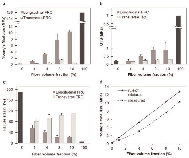
Unidirectional non-crimped fiber reinforced composites exhibited stiffening in the direction of the oriented fibers. In particular, Young’s modulus increased from 0.95 ± 0.35 to 10.4 ± 0.5 MPa, UTS increased from 0.22 ± 0.08 to 0.87 ± 0.5 MPa, and failure strains decreased as the volume fraction of fibers increased within a composite film (Fig. 7a–c). When loaded perpendicular to the long axis of the fibers, mechanical properties resembled that of the elastin-like matrix with failure observed at the fiber-matrix interface. Given the low frequency of bridges along each fiber, their presence did not influence the mechanical response when the composite was loaded perpendicular to the direction of the aligned fibers. Native blood vessels are reported to exhibit a Young’s modulus of 1–5 MPa, ultimate tensile strength of 0.3–11 MPa, and strain to failure of 40–160 %.[36]–[40] Although further optimization would be required, the mechanical properties of the engineered materials lie within the cited range for native tissues.
Figure 7.
(a) Young’s modulus, (b) ultimate tensile strength, and (c) strain-to-failure for unidirectional straight fiber composites with volume fractions of 1, 4, 8, and 10 %. Fiber volume fraction of 0 and 100% indicate elastin-like protein matrix and collagen fibers, respectively. Fiber reinforced composites were oriented either parallel or perpendicular to the long fiber axis for measurement of longitudinal and transverse properties, respectively. (d) Measured and estimated influence of the fiber volume fraction on the Young’s modulus of elasticity.
In principle, the fibers and matrix in a composite material function together to exhibit properties that combine features of both constituents. The stiffness in the direction of the fiber alignment can be estimated by a sum of fractions of the individual component properties using the ‘rule of mixtures’:
| (2) |
where Ec = Young’s modulus of the FRC, Ef = Young’s modulus of the fibers, Vf = fiber [41] volume fraction, Em = Young’s modulus of the matrix, and Vm = matrix volume fraction. As predicted, increasing the fiber volume fraction results in stiffer materials (Fig. 7d). Observed discrepancies may have resulted from errors in determining fiber volume fraction.
Strain dependent mechanical responses were observed for in-plane crimped FRCs with a Young’s modulus dominated by the elastin-mimetic matrix at low strains, slightly augmented by bending of the collagen fibers. At higher strains, as the fibers started to straighten, the material displayed a high modulus of elasticity characteristic of the stiffer fibers (Fig. 8a). This transition from a low to high modulus regimes was dictated by the designed transition strain calculated as a ratio of the differential of the arc length and wavelength of the fiber crimp to the wavelength of the fiber crimp:
| (3) |
where εd = designed crimp transition strain, L = crimp arc length, and λ = crimp wavelength (Fig. 8b). For a designed strain of 27.4%, the measured transition occurred at 20 ± 2.7 % implying premature stiffening, which may be attributed to the bending stiffness of in-plane crimped fibers.
Figure 8.
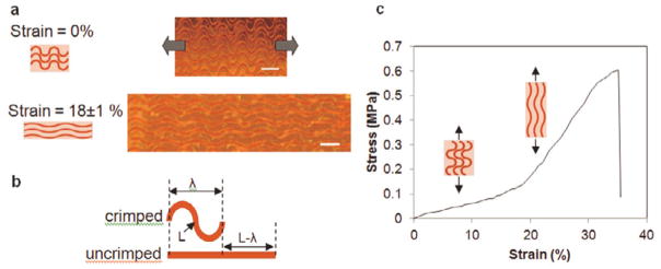
(a) Straightening of fiber undulations with an increasing tensile strain. Microscope images illustrate a fiber network at 0% and 18±1% strains (scale bars 100 μm). (b) A schematic for the designed transition strain of the in-plane fiber crimps. (c) Representative stress-strain curve displays a transition from a low to a high stiffness regime for an in-plane crimped fiber composite.
At a fiber volume fraction of 4%, the Young’s modulus was observed to transition from 0.7 ± 0.14 MPa to 3.15 ± 0.49 MPa forming a toe-region similar to that observed in many native soft tissues (Fig. 8c). The collagen fibers were stained using Van Gieson’s. The composite materials were inspected using an optical microscope. As anticipated, the modulus in the low strain region (< 10%) of composites containing crimped fibers was comparable to, albeit slightly higher, than the modulus of the elastin-like matrix alone (0.25 ± 0.21 MPa). At higher strains (> 20%), the modulus of the material was consistent with the modulus of straight fiber composites with a volume fraction of 4% (3.1 ± 0.42 MPa). The reported low and high strain modulii for native blood vessels are 0.2–1.1 MPa and 1.5–5.2 MPa, respectively. The transition strains may range from 25–120 %.[36]–[37], [42]
3. Conclusions
An alternative approach to conventional extrusion-based techniques for the fabrication of collagen microfibers was designed through the development of a microtransfer molding process. MEMS processing facilitated the fabrication of precise fiber architectures through the creation of simple template modifications. Notably, D-periodic collagen microfibers could be reproduced from the deposition of monomeric collagen. Fiber dimensions are only constrained by the limits of the photolithography process and, in principle, this approach can be extended to the fabrication of sub-micron scale fibers. Hollow fiber networks also offer the potential for drug delivery by constructing fibers loaded with drug particles or cell-based therapeutics.
Collagen fiber networks were encased within a recombinant elastin-like protein polymer matrix to form a fiber reinforced protein composite. Significantly, engineering bridges between fibers supported facile 3-dimensional organization by limiting deformation and entanglements of the fiber network during transfer of the fibers to the elastin-like protein matrix.
Several soft tissues are composed of crimped collagen fibers and display strain dependent mechanical responses. A crimped fiber network was engineered with fiber undulations to introduce non-linear dual-elastic behavior. The material transitioned from a low to high stiffness regime at a transition strain determined by the designed crimp geometry.
In conclusion, these studies demonstrated that microtransfer molding from MEMS derived templates can be used to generate well defined fiber microstructures and, as a consequence, composite systems with tunable mechanical responses. Significantly, fiber concentration, orientation, and layout were all important determinants in the design of versatile protein-based composites that display both robust strength and extensibility.
4. Experimental
Materials
Collagen type I was isolated from Sprague-Dawley rat tail tendons, as detailed elsewhere [12]. A recombinant elastin-mimetic protein polymer, LysB10, was expressed from E. coli and purified, as detailed elsewhere.[[26]]
Fabrication of spatially designed collagen fiber reinforced elastin-like protein polymer composites
Micromolding templates were fabricated on (100) silicon wafers. A positive photoresist (Microposit SC 1827, Shipley, Marlborough, MA) was spin coated on the wafer and patterned using photolithography to define the in-plane fiber network design. The patterns were etched into the silicon wafer using inductively coupled plasma (ICP, Bosch process, SF6/CF4) etching. After photoresist removal with acetone, the silicon template was treated with a parylene adhesion promotion agent (3-(trimethoxysilyl) propyl methacrylate, Aldrich). A thin film (600 – 800 nm) of parylene was then deposited on the template. Solvent casting was used to cast a conformal collagen film from solubilized collagen in 10 mM HCl onto the template that was subsequently dried under vacuum (8 kPa). The solvent cast collagen film was neutralized with an alkaline buffer solution (BS, 4.14 mg/mL monobasic sodium phosphate, 12.1 mg/mL dibasic sodium phosphate, 6.86 mg/mL TES (N-tris (hydroxymethyl) methyl-2-aminoethane sulfonic acid sodium salt), 7.89 mg/mL sodium chloride) and 0.1 mM sodium hydroxide (NaOH) (BS:NaOH, 2:1, pH 11) for 10 hours at 37°C. The resultant collagen film was crosslinked in vapor phase glutaraldehyde (0.5 wt% glutaric acid dialdehyde in 1× phosphate buffered saline (PBS)). A thin layer of water-soluble polymer, polyvinyl pyrrolidone (PVP, MW 1,300 kDa, 10 mg/mL in water, film thickness: 10 μm), was solvent cast onto the collagen film. Dry mechanical polishing and oxygen plasma RIE were used for creating individual collagen microfibers in the trenches. A second layer of PVP (MW 1,300 kDa, 22 mg/mL in water, film thickness: 50 μm) was cast. The collagen fiber network was demolded using a water-soluble tape (1stMaskingTape Inc., Torrance, CA).
For silicon templates for out-of-plane crimped fibers, a 1 μm thick SiO2 layer grown on a silicon wafer using wet thermal oxidation (2.5 h, 1100°C). Straight patterns were defined in the SiO2 layer using photolithography (with photoresist Microposit SC 1827, Shipley, Marlborough, MA) and ICP etching of SiO2. The photoresist was etched using acetone and RIE (oxygen plasma). Straight photoresist (Microposit SC 1827, Shipley, Marlborough, MA) patterns were defined perpendicular to the SiO2 straight patterns and ICP etching (Bosch process, SF6/CF4) was used to partially etch silicon as described earlier. The photoresist layer was etched using acetone and RIE (oxygen plasma) followed by a final ICP (Bosch process, SF6/CF4) etching step. The silicon template was immersed in a KOH bath (40%, 80 °C). Sequential spray coating was used to cast collagen (solubilized in 10 mM HCl) onto the template. The individual fiber network was then transferred to a water-soluble tape (1stMaskingTape Inc., Torrance, CA).
A solution of elastin-like protein polymer, LysB10, (50 mg/mL in water) was cast onto the collagen fiber network at 4°C. The elastin film was gelled at 37°C for 1 hour and the water-soluble film subsequently dissolved in water at 37°C, leaving behind collagen fibers embedded in the elastin-like protein polymer matrix. Collagen fibers were stained using Van Gieson’s and inspected by optical microscopy. Multi-lamellar composites were fabricated by stacking and incubating individual sheets at 4°C for 17 h to liquefy and fuse the elastin-like matrix, which were compressed to a final film thickness of 100 μm using plastic spacers, and then crosslinked in a 0.5% glutaraldehyde solution.
Atomic Force Microscope (AFM) imaging of the collagen fiber structure
The fibrillar structure of the fabricated collagen fibers was examined by AFM (Veeco nanoscope, CA). The collagen fiber network was mounted onto a silicon chip (2 cm × 2 cm) and the edges of the network were secured using water-soluble tape. The tape and PVP were removed by dissolution in water and the fibers allowed to dry on the silicon substrate. Collagen fibrils were investigated by scanning ten, 2 μm × 2 μm areas, in each network.
Microscopic analysis
All fiber dimensions and layouts were examined using scanning electron microscopy (SEM). Collagen fibers were stained using Van Gieson’s and inspected by optical microscopy.
Mechanical characterization of collagen microfibers, elastin-like protein matrix, and collagen fiber reinforced composites
Uniaxial stress-strain mechanical properties of collagen fiber networks, the elastin-like matrix, and composite materials were derived using dynamic mechanical analysis (DMA, Rheometeric Inc.) at a constant strain rate of 0.64%/sec until failure. Individual collagen fibers were isolated by dissolving the water-soluble film that secured them and mounted onto a plastic frame. Elastin-like sheets were obtained from films cast from an aqueous solution (50 mg/mL) onto a glass substrate. Specimens were hydrated by immersing the sample mount in PBS at 37°C for the duration of the applied load.
Acknowledgments
This project was supported by NIH (R01 HL 083867). The fabrication was performed at Nanotechnology Research Center (NRC) at Georgia Institute of Technology. The authors wish to thank Mr. Richard Shafer for his support on the project and Dr. Vivek Kumar for providing collagen material.
Contributor Information
Dr. Nisarga Naik, Department of Surgery, Harvard Medical School, Beth Israel Deaconess Medical Center Boston, MA 02115, USA, Wyss Institute of Biologically Inspired Engineering of Harvard University Boston, MA 02115, USA, School of Electrical and Computer Engineering, Georgia Institute of Technology Atlanta, GA 30332, USA
Dr. Jeffrey Caves, Department of Surgery, Harvard Medical School, Beth Israel Deaconess Medical Center Boston, MA 02115, USA, Wyss Institute of Biologically Inspired Engineering of Harvard University Boston, MA 02115, USA
Prof. Elliot Chaikof, Email: echaikof@bidmc.harvard.edu, Department of Surgery, Harvard Medical School, Beth Israel Deaconess Medical Center Boston, MA 02115, USA, Wyss Institute of Biologically Inspired Engineering of Harvard University Boston, MA 02115, USA, Harvard Stem Cell Institute Boston, MA 02115, USA
Prof. Mark G. Allen, Email: mark.allen@ece.gatech.edu, School of Electrical and Computer Engineering, Georgia Institute of Technology Atlanta, GA 30332, USA
References
- 1.Freed D, Doehring TC. J Biomech Eng. 2005;127:587. doi: 10.1115/1.1934145. [DOI] [PubMed] [Google Scholar]
- 2.Matthews JA, Wnek GE, Simpson DG, Bowlin GL. Biomacromolecules. 2002;3:232. doi: 10.1021/bm015533u. [DOI] [PubMed] [Google Scholar]
- 3.Rho KS, Jeong L, Lee G, Seo BM, Park YJ, Hong SD, Min BM. Biomaterials. 2006;27:1452. doi: 10.1016/j.biomaterials.2005.08.004. [DOI] [PubMed] [Google Scholar]
- 4.Carlisle R, Coulais C, Guthold M. Acta Biomater. 2010;6:2997. doi: 10.1016/j.actbio.2010.02.050. [DOI] [PMC free article] [PubMed] [Google Scholar]
- 5.Matthews JA, Boland ED, Wnek GE, Simpson DG, Bowlin GL. J Bioact Compat Polym. 2003;18:125. [Google Scholar]
- 6.Schimpf WC, Rodriguez F. Ind Eng Chem Prod RD. 1977;16:90. [Google Scholar]
- 7.Dunn MG, Avasarala PN, Zawadsky JP. J Biomed Mater Res. 2004;27:1545. doi: 10.1002/jbm.820271211. [DOI] [PubMed] [Google Scholar]
- 8.Zeugolis DI, Paul GR, Attenburrow G. J Biomed Mater Res A. 2009;89:895. doi: 10.1002/jbm.a.32031. [DOI] [PubMed] [Google Scholar]
- 9.Pins GD, Huang EK, Christiansen DL, Silver FH. J Appl Polym Sci. 1997;63:1429. [Google Scholar]
- 10.Ming-Che W, Pins GD, Silver FH. Biomaterials. 1994;15:507. doi: 10.1016/0142-9612(94)90016-7. [DOI] [PubMed] [Google Scholar]
- 11.Zeugolis DI, Paul RG, Attenburrow G. J Biomed Mater Res A. 2007;86:892. doi: 10.1002/jbm.a.31694. [DOI] [PubMed] [Google Scholar]
- 12.Caves JM, Kumar VA, Wen J, Cui W, Martinez A, Apkarian R, Chaikof EL. J Biomed Mater Res B. 2010;93:24. doi: 10.1002/jbm.b.31555. [DOI] [PMC free article] [PubMed] [Google Scholar]
- 13.Buttafoco L, Kolkman NG, Engbers-Buijtenhuijs P, Poot AA, Dijkstra PJ, Vermes I, Feijen J. Biomaterials. 2006;27:724. doi: 10.1016/j.biomaterials.2005.06.024. [DOI] [PubMed] [Google Scholar]
- 14.McClure MJ, Sell SA, Simpson DG, Bowlin GL. J Eng Fiber Fabr. 2009;4:18. [Google Scholar]
- 15.Stitzel J, Liu J, Lee SJ, Komura M, Berry J, Soker S, Atala A. Biomaterials. 2006;27:1088. doi: 10.1016/j.biomaterials.2005.07.048. [DOI] [PubMed] [Google Scholar]
- 16.Boland ED, Matthews JA, Pawlowski KJ, Simpson DG, Wnek GE, Bowlin GL. Front Biosci. 2004;9:1432. doi: 10.2741/1313. [DOI] [PubMed] [Google Scholar]
- 17.Zeugolis DI, Khew ST, Yew ES, Ekaputra AK, Tong YW, Yung LYL, Raghunath M. Biomaterials. 2008;29:2293. doi: 10.1016/j.biomaterials.2008.02.009. [DOI] [PubMed] [Google Scholar]
- 18.Caves JM, Kumar VA, Martinez AW, Kim J, Ripberger CM, Haller CA, Chaikof EL. Biomaterials. 2010;31:7175. doi: 10.1016/j.biomaterials.2010.05.014. [DOI] [PMC free article] [PubMed] [Google Scholar]
- 19.Caves JM, Kumar VA, Xu W, Naik N, Allen MG, Chaikof EL. Adv Mater. 2010;22:2041. doi: 10.1002/adma.200903612. [DOI] [PMC free article] [PubMed] [Google Scholar]
- 20.Lu Y, Mapili G, Suhali G, Chen S, Roy K. J Biomed Mater Res A. 2006;77:396. doi: 10.1002/jbm.a.30601. [DOI] [PubMed] [Google Scholar]
- 21.Liu A, Bhatia SN. Biomed Microdevices. 2002;4:257. [Google Scholar]
- 22.Mapili G, Lu Y, Chen S, Roy K. J Biomed Mater Res B. 2005;75:414. doi: 10.1002/jbm.b.30325. [DOI] [PubMed] [Google Scholar]
- 23.Zorlutuna P, Elsheikh A, Hasirci V. Biomacromolecules. 2009;10:814. doi: 10.1021/bm801307y. [DOI] [PubMed] [Google Scholar]
- 24.Rago P, Chai PR, Morgan JR. Tissue Eng Pt A. 2008;15:387. doi: 10.1089/ten.tea.2008.0107. [DOI] [PubMed] [Google Scholar]
- 25.Naik N, Caves J, Kumar V, Chaikof E, Allen MG. Proceedings of Solid-State Sensors, Actuators and Microsystems Conference-Transducers; 2009. p. 1869. [DOI] [PMC free article] [PubMed] [Google Scholar]
- 26.Sallach RE, Cui W, Wen J, Martinez A, Conticello VP, Chaikof EL. Biomaterials. 2009;30:409. doi: 10.1016/j.biomaterials.2008.09.040. [DOI] [PMC free article] [PubMed] [Google Scholar]
- 27.Gough JE, Scotchford CA, Downes S. J Biomed Mater Res. 2002;61:130. doi: 10.1002/jbm.10145. [DOI] [PubMed] [Google Scholar]
- 28.Sung HW, Huang RN, Huang LL, Tsai CC. J Biomater Sci Polym Ed. 1999;10:63. doi: 10.1163/156856299x00289. [DOI] [PubMed] [Google Scholar]
- 29.McPherson JM, Sawamura S, Armstrong R. J Biomed Mater Res. 1986;20:93. doi: 10.1002/jbm.820200109. [DOI] [PubMed] [Google Scholar]
- 30.Meade KR, Silver FH. Biomaterials. 1990;11:176. doi: 10.1016/0142-9612(90)90151-f. [DOI] [PubMed] [Google Scholar]
- 31.Scotchford CA, Cascone MG, Downes S, Giusti P. Biomaterials. 1998;19:1. doi: 10.1016/s0142-9612(97)00236-6. [DOI] [PubMed] [Google Scholar]
- 32.McClure MJ, Sell SA, Barnes CP, Bowen WC, Bowlin GL. J Eng Fiber Fabr. 2008;1:1M. [Google Scholar]; Venturoni T, Gutsmann, Fantner GE, Kindt JH, Hansma PK. Biochem Bioph Res Co. 2003;303:508. doi: 10.1016/s0006-291x(03)00390-5. [DOI] [PubMed] [Google Scholar]
- 33.Guo, Kaufman LJ. Biomaterials. 2007;28:1105. doi: 10.1016/j.biomaterials.2006.10.010. [DOI] [PubMed] [Google Scholar]
- 34.Rosner I, Dubey N, Letourneau PC, Tranquillo RT. Engineering in Medicine and Biology 21st Annu. Conf; 1999. p. 117. [Google Scholar]
- 35.Köster S, Leach JB, Struth B, Pfohl T, Wong JY. Langmuir. 2007;23:357. doi: 10.1021/la062473a. [DOI] [PubMed] [Google Scholar]
- 36.Kurane A, Simionescu DT, Vyavahare NR. Biomaterials. 2007;28:2830. doi: 10.1016/j.biomaterials.2007.02.031. [DOI] [PMC free article] [PubMed] [Google Scholar]
- 37.Silver FH, Snowhill PB, Foran DJ. Ann Biomed Eng. 2003;31:793. doi: 10.1114/1.1581287. [DOI] [PubMed] [Google Scholar]
- 38.Dahl SL, Rhim C, Song YC, Niklason LE. Ann Biomed Eng. 2007;35:348. doi: 10.1007/s10439-006-9226-1. [DOI] [PMC free article] [PubMed] [Google Scholar]
- 39.Danpinid A, Luo J, Vappou J, Terdtoon P, Konofagou EE. Ultrasonics. 2010;50:654. doi: 10.1016/j.ultras.2010.01.003. [DOI] [PMC free article] [PubMed] [Google Scholar]
- 40.Holzapfel GA. The Handbook of Materials Behavior Models. Academic Press; 2001. p. 1049. [Google Scholar]
- 41.Askeland R, Fulay PP, Wright WJ. The Science and Engineering of Materials. Ch 17 Thomson Engineering; 2011. [Google Scholar]
- 42.Carmines DV, McElhaney JH, Stack R. J Biomech. 1991;24:899. doi: 10.1016/0021-9290(91)90168-m. [DOI] [PubMed] [Google Scholar]


