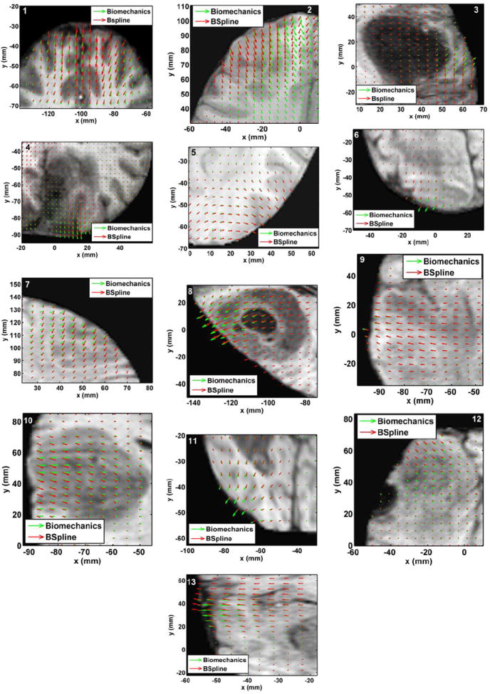
FIGURE 7.

The predicted deformation fields overlaid on an axial slice of pre-operative image. An arrow represents a 2D vector consisting of the x (R-L) and y (A-P) components of displacement at a voxel centre. Green arrows: deformation field predicted by the biomechanical model. Red arrows: deformation field calculated by the BSpline algorithm. The number on each image denotes a particular neurosurgery case.
