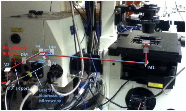
Fig. 2.

Image of an Olympus FW1000 system overlaid with both the OCT sample arm and fluorescence excitation beam paths. The broadband infrared light for OCT and the lasers for the fluorescence microscopy are shown as red and blue, respectively. M, M1–3: mirror, DM: dichroic mirror, GM1,2: galvanometric mirror, PMT: photomultiplier tube, F: optical band path filter.
