
Figure 1.
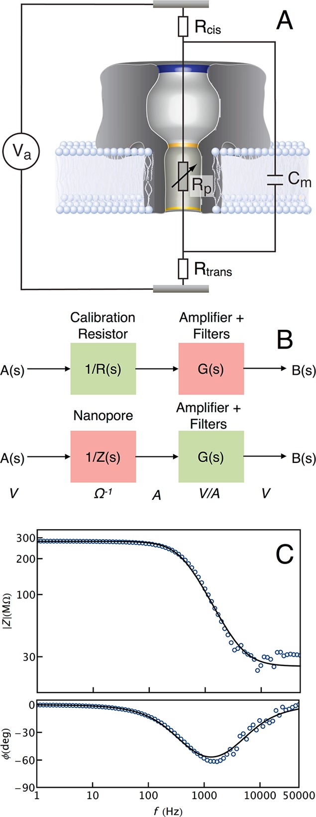
(A) Equivalent circuit model of the nanopore system. The nanopore and membrane are modeled as a resistor (Rp) and capacitor (Cm) in parallel, together with the total solution and access resistances on either side of the membrane (Rcis and Rtrans). (B) The nanopore impedance is measured after removing artifacts from the measurement apparatus. First, the transfer function of the measurement apparatus is determined from the response (B(s)) of a 300 MΩ calibration resistor to a swept sinusoidal voltage (A(s)) stimulus (top). Assuming the resistor frequency response is flat, G(s) = (B(s)/A(s)) R(s), where G(s) and R(s) are the transfer functions of the measurement apparatus and the calibration resistor respectively. The corrected nanopore impedance was then determined in an identical manner (bottom) to yield Z(s) = G(s)/(B(s)/A(s)). (C) The equivalent circuit model was validated by measuring the impedance of the nanopore–membrane complex as a function of frequency (blue markers). A least-squares fit (black) of eq 1 to the measured data yielded estimates of Rp = 255 MΩ, Rcis = Rtrans = 14 MΩ, and Cm = 1.6 pF.