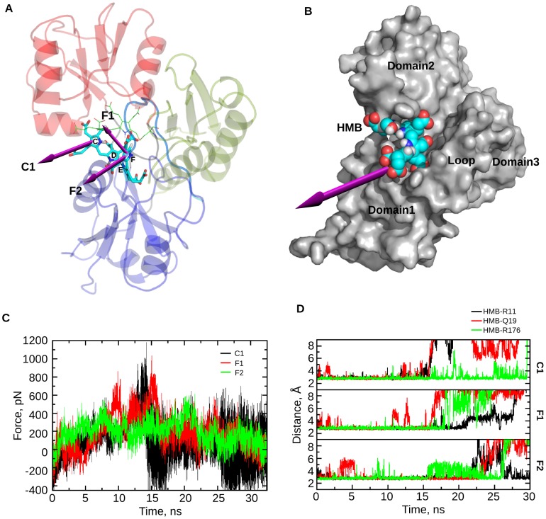
Figure 11. Exit mechanism of HMB from PBGD.
A. Structure of PBGD showing probable exit directions, either from C or F ring of the HMB unit, that are considered for SMD simulations: C1 (Direction from the center of mass of the C ring in HMB towards the interface of domain 1 and domain 2), F1 (Direction from the center of mass of the F ring in HMB towards the active site loop), F2 (Direction from the center of mass of the F ring in HMB towards the interface between the active site loop and domain 1). B. Surface representation of the structure of PBGD showing the most probable path predicted for the exit of HMB through the space between domain 1, domain 2 and the active site loop (Video S3). C. Force as a function of time during the SMD runs in 3 different exit paths: C1, F1 and F2. D. Graphs showing the interactions of R11, Q19 and R176 with HMB during the SMD runs through C1, F1, and F2 path, indicating the possible role of these catalytically important residues in the exit of the product.

