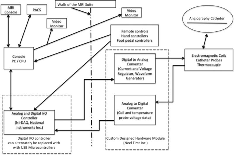
Fig. 3.
Overview of MARC catheter control system hardware configuration. The catheter with electromagnetic tip is represented in the upper right hand corner of the figure. Major components are labeled within boxes and arrows represent data flow. Alternate hardware configurations have been developed, which integrate USB microcontrollers onto the custom hardware PCB module and onto footswitch to relay digital communication via USB to the PC without necessitating the NI-DAQ controller.

