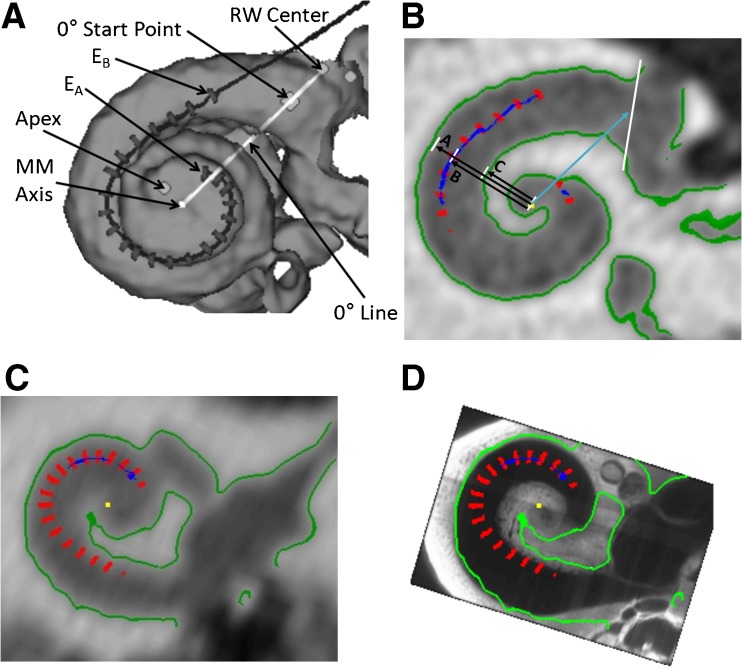
FIG. 1.
Methods for distance measures. A The dark line and gray hash marks show the path of the array and the location of the 22 electrode contacts of a Contour Advance™ array (E A apical-most electrode, E B basal-most electrode). Shown are the center of the round window (RW), the cochleostomy site, the 0 ° start point, the apex of the cochlea, the mid modiolar axis and the 0 ° reference line. B The distance from the mid-modiolar (MM) axis to the inner wall "C", from the MM axis to the electrode "B", and from the MM axis to the outer wall "A" are shown here for S41’s electrode 6. This is a slice through the cochlea looking down the mid-modiolar axis. We use the information to determine the electrode to modiolus medial–lateral (EMML) distance, "B" minus "C". C The electrode positions (red) relative to the clinical CT in greyscale with boundaries derived from the clinical CT in green for a participant with a low resolution pre-operative scan. D The same electrode positions and boundaries relative to the aligned OPFOS cochlea. The boundaries of the cochlea from the clinical CT are less clear toward the apex (i.e., the green boundary stops), while the boundary identified by the OPFOS template continues. Using the OPFOS image allows EMML distance measures to be made at the apex.

