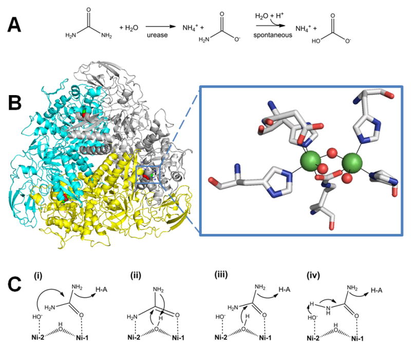
Fig. 3.

Urease. (A) The reaction catalyzed by urease. (B) Urease structure and active site. The detailed architectures differ for different ureases, but all include a trimeric configuration of 1, 2, or 3 subunits. The urease shown (cartoon view, PDB access code 1fwj, Klebsiella aerogenes) possesses three subunits in uniform color (cyan, yellow, or white). Each active site contains two Ni (green spheres) that are bridged by a Lys carbamate and a water, with each Ni also binding a terminal water and two His, plus an Asp coordinating to one metal (side chains as sticks and solvent as red spheres). (C) Four reaction mechanisms proposed for urease. Proposals for urease catalysis are unified by having the urea carbonyl oxygen coordinated to Ni-1. (i) Hydroxide bound to Ni-2 attacks the urea carbonyl carbon to form a tetrahedral intermediate that decomposes with a nearby His residue functioning as a general acid. (ii) The bridging hydroxide attacks the urea carbonyl carbon while transferring its proton to product ammonia, with the other urea amine coordinated to Ni-2. (iii) The bridging hydroxide attacks the urea carbonyl carbon to form a tetrahedral intermediate that decomposes with a nearby His residue functioning as a general acid. (iv) A general base (perhaps Ni-2 coordinated hydroxide as shown) abstracts a urea proton leading to elimination of ammonia and production of cyanate that is subsequently hydrated.
(2 column width)
