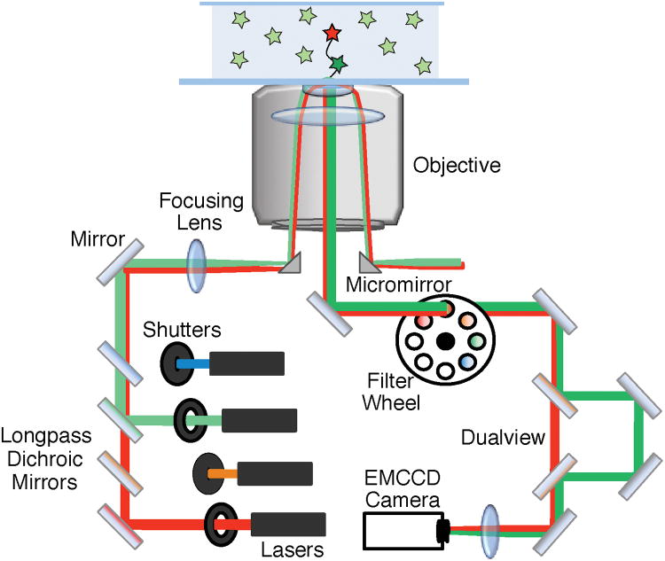
Figure 2.
The basic components of an objective-based mmTIRF microscope. This diagram shows simultaneous excitation using both a red and green laser (red and green lines). The beams are combined using longpass dichroic mirrors and directed onto the back aperture of the objective using a micromirror. TIR occurs at the interface of the slide and the solution containing the fluorescent sample resulting in selective excitation of molecules near the surface. The excitation beam is directed out of the objective and away from the emission path using a second micromirror. The emission signal from the excited fluorophores (shown in the center of the objective) is directed to the EMCCD camera using a 45° mirror. Residual laser light can be removed using filters. In this diagram, emission signal from the green fluorophore is spatially separated from the red fluorophore emission using a dualview apparatus. The emission signals are focused onto an EMCCD camera – generating separate images for the green and red fluorophores.

