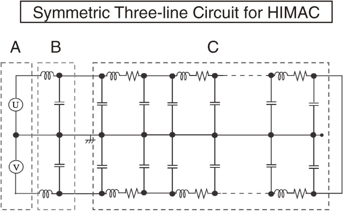
Figure 1.
Example of a schematic diagram of the S3L circuit with the electric circuit of a power supply (A), noise filter (B) and magnet system (C) used for HIMAC.1) There are three-conductor transmission lines and all the electric components are symmetrically arranged around the central ground line. The left part (A) is for the twin power supplies, U and V, connected in series, and the second one (B) is the symmetrically arranged filtering devices for the reduction of high frequency noises. The third part (C) is for a chain of magnets consisting of a coil with resistance, whose body is connected to the central ground line. The left end of the central ground line is connected to the middle point of the twin power supplies and the right end is not connected (open) to the main two lines without considering the impedance matching. This is an example of the S3L circuit, where all of the electric devices are placed symmetrically around the central ground line in order to reduce the noise.

