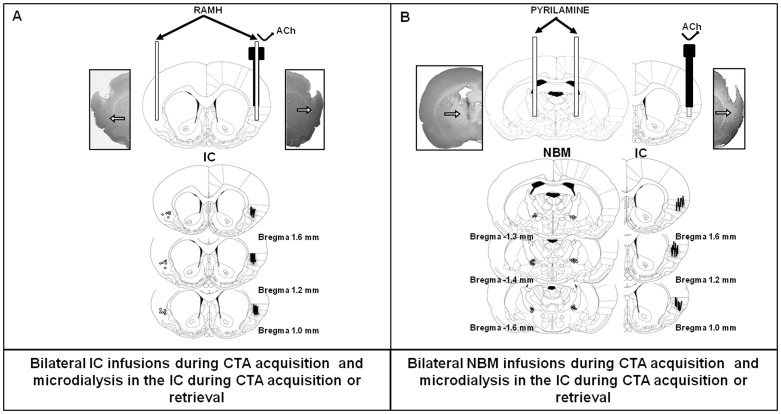
Figure 1. Coronal section diagrams and representative photomicrographs of the IC and NBM.
Arrows in photomicrographs and dots in atlas diagrams show locations of stainless-steel cannulae; lines shows microdialysis probe trails. A) One stainless-steel cannula implanted in the left IC and one dual probe (with injector and cannula) implanted in the right IC. B) Stainless-steel cannulae placed bilaterally in the NBM and one cannula/microdialysis probe in the right IC.

