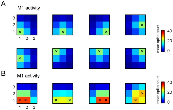
Figure 3. Examples of stimulus-response S1-M1 model used to run the interface.
We report some examples of trial-averaged neural responses by our model M1 in response to selected patterns of stimulations of S1. Here we plot responses for the case in which recording electrodes are arranged in a  grid (as in the stimulus set number 6 that has 32 elements (see Table 1) and was used in most of the simulations). As explained in the main text, the spikes evoked by stimulating each S1 electrode are modeled by bivariate Gaussian distributions that peak in the corresponding M1 recording sites. (A) The average number of simulated spikes recorded from the electrodes in M1 and evoked by stimulating a single electrode in S1 (stimulated electrode is represented by a superimposed black “x”). (B) Average number of simulated M1 spikes evoked by stimulating couples of electrodes in S1 (again the pair of stimulated electrodes is indicated by the superimposed black “x”). In both panels, the color scale indicates the mean spike count expressed in units of mean spike count per trial, and the responses were shown for only one of the possible four levels of intensity in which each electrode could be stimulated in stimulus set number 6 (see Table 1).

