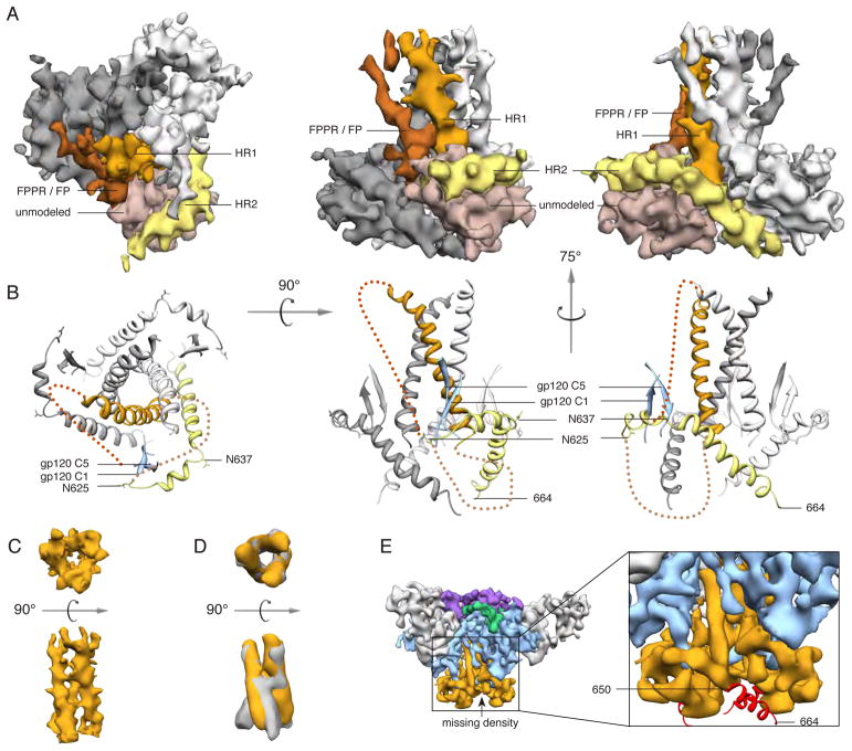
Fig. 3. Structure of gp41.
(A) Segmented EM density map of the gp41 trimer with gp120 removed. The C-terminal half of HR1 (rust) forms a three-helix bundle at the center of the trimer, while the C-terminal half of HR2 (yellow) forms a helical structure that wraps around the trimer base. Additional density that is not assigned in the model (beige) likely corresponds to the intervening region between HR1 and HR2, including the disulfide loop, as well as C1 and C5 from gp120. Density parallel to HR1 (brown) likely corresponds to the N-terminal half of HR1, the fusion peptide proximal region (FPPR) and the fusion peptide (FP). (B) Modeled portion corresponding to the same views of the EM density maps in A. (C) EM density of the three-helix bundle formed by HR1 in the PGV04-bound trimer structure. (D) Overlay of the EM density of the three-helix bundle formed by HR1 in the PGV04-bound structure that is filtered to 9.5 Å (orange) with the 9 Å reconstruction of a 17b-bound SOSIP gp140 trimer (gray, EMDB-5462) (35). (E) An 8.2 Å reconstruction of a SOSIP trimer from which the last 14 amino acids were deleted (SOSIP.650:PGV04). The difference between the SOSIP.650 and SOSIP.664 maps corresponds to a short helical segment (red) at the end of HR2, that projects toward the adjacent protomer (see also fig. S8).

