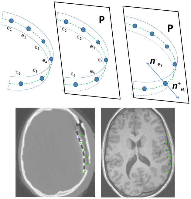
Fig 6.
(Row 1): Strip electrodes e1, …,e6; (blue circles) are mounted on a narrow rectangular plastic sheet which is bent in one direction during implantation. The hypothetical dashed green line l on the plastic sheet connects the centers of the electrodes (left). Due to the rectangular shape of the plastic sheet, the electrode centers are roughly located on one plane, P, even after the strip is bent; this plane is estimated using the linear least square method (middle). The two normal vectors, and , are in plane P, and perpendicular to both line l and the plastic sheet, which show the projection directions. (Row 2): illustrates the projection of a 6×1 strip array onto the MRI cortical surface using the proposed method. First, the CT image is registered on the MRI image, and then, the electrode centers on the CT image (blue spheres) are displaced in direction normal to the plastic sheet which can be distinguished as a dark line connecting the high intensity electrodes on the CT image. As seen in the MRI image, the electrodes are accurately projected on the MRI cortical surface before craniotomy (green spheres).

