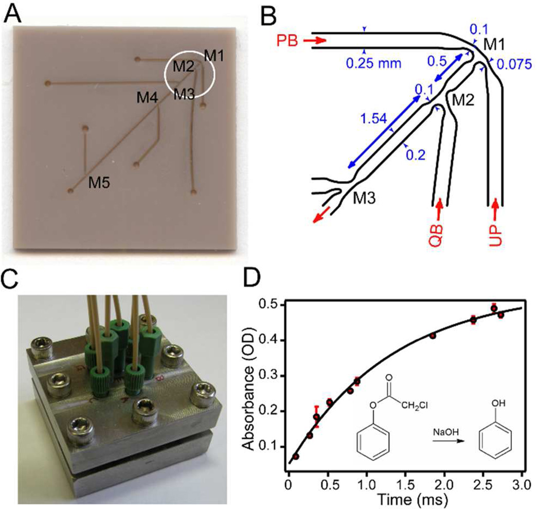
Figure 1.
Microfluidic mixing device. A. Photograph of PEEK chip (25×25 mm2) showing laser microfabricated surface features, including mixing regions M1 through M5 and access channels. B. Schematic of an expanded region (circled in A) covering mixing regions M1 through M3. PB: high-pH pulse buffer in H2O; UP: unfolded protein in D2O; QB: low-pH quench buffer in H2O. C. Photograph of the steel holder containing the multi-mixer chip illustrated in A. D. Calibration of the mixing device using alkaline hydrolysis of phenol chloroacetate (PCA; inset). The absorbance of the product (phenol) was measured at 270 nm vs. aging time.

