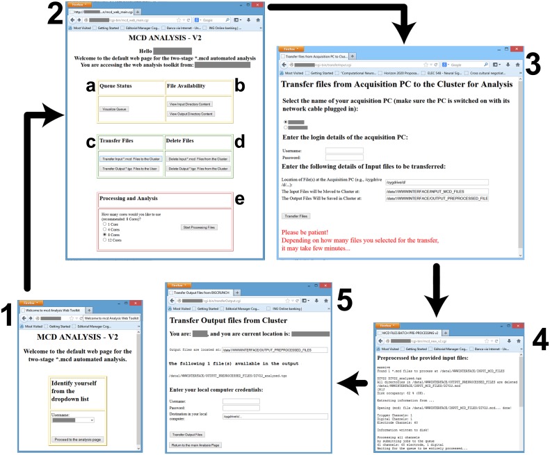
Figure 4.
Screenshots of the web-interface. Each window is numbered to denote a separate stage of the workflow, and consist in: (1) the user-identification; the (2) main control webpage; the (3) file transfer interface from the data acquisition PC to the master node; (4) the result of the preprocessing; and (5) the file transfer from the master node to the user PC. Individual letter labels in (2) represent grouped functionalities, such as the visualization (a) of the status of the computing queues, the availability check (b) for the data files in the input and output directories, the file transfer and management functions (c,d), and finally (e) the initiation of the parallelized preprocessing and analysis, with an option to select the destination queue.

