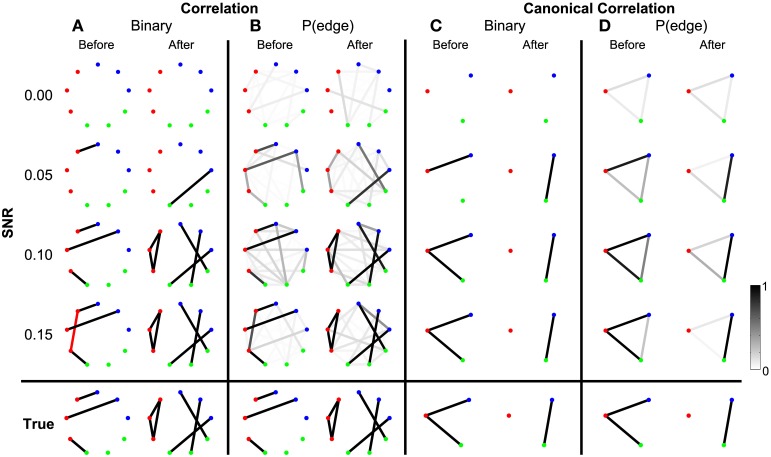
Figure 3.
Detected networks reflect the true correlation structure for sufficiently high SNR. Correlation and canonical correlation networks are shown before and after task onset, for simulations with varying SNR. (A) Binary correlation networks for 500 ms before task onset (left) and the 500 ms after task onset (right). True positive edges are colored black, false positive edges are colored red. (B) Bootstrapped probability of each edge for the correlation before (left) and after (right) networks. Probabilities are indicated in grayscale from 0 (white) to 1 (black); scale bar at bottom right of the figure. (C) The same as (A), but for canonical correlations between regions. (D) The same as (B), but for canonical correlations between regions. Plots (A–D) are shown in the rows for four different levels of SNR: 0.00, 0.05, 0.10, and 0.15. True networks are shown in the bottom row. In all networks, nodes are color-coded according to region.

