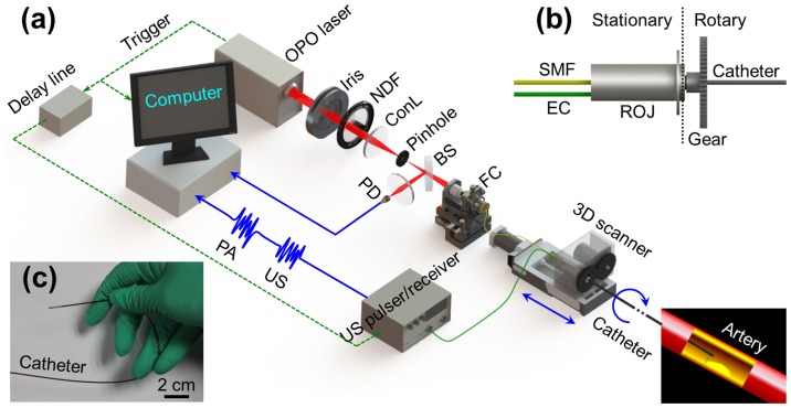
Figure 1. Illustration of the OR-PAT system.
(a) Overall architecture of the system. (b) Schematic of the rotational mechanism of the catheter. (c) A photo of the catheter showing its flexibility. OPO, optical parametric oscillator; NDF, neutral density filter; ConL, condenser lens; BS: beam splitter; PD, photodiode; FC, fiber coupler; US, ultrasonics; PA, photoacoustics; SMF, single mode fiber; EC, electrical cable; 3D scanner, consisting of an optical-electric rotary joint (ROJ), a step motor, and a motorized pull-back stage.

