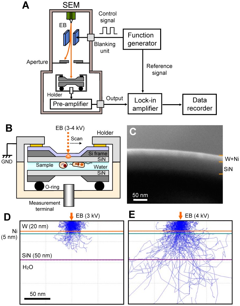
Figure 1. Experimental set-up and data acquisition system.
(A) FTE imaging system. The scanning EB irradiates the upper side of the W–Ni-coated SiN film, which is modulated by the beam-blanking unit using a function generator at 30−60 kHz. The output signal from the lock-in amplifier is recorded by a data recorder. (B) Schematic of the atmospheric sample holder. The two SiN films with the liquid sample are sealed by the two sample-holding parts with double-sided tape, and the holding pieces are coupled using screws. The sample holder consists of an upper aluminium part and a lower acrylic resin. The wet biological specimens are enclosed in two SiN films: the upper side of the SiN film is coated with a W and Ni layer and connected to the system GND. (C) SEM cross-sectional image of a metal-coated SiN film consisting of a 20-nm-thick W layer, 5-nm Ni layer, and 50-nm SiN film. (D) MC simulation of the electron trajectories in the W–Ni-coated SiN film at 3-kV EB. The irradiated electrons are completely scattered and absorbed in the film. (E) MC simulation of 4-kV EB. A few electrons reach the water layer. Scale bars (C) and (D) 50 nm.

